


OM-169 510 Page 1
SECTION 1 – SAFETY PRECAUTIONS AND SIGNAL WORDS
1-1. GENERAL INFORMATION AND SAFETY
A. General
Information presented in this manual and on various la-
bels, tags, and plates on the unit pertains to equipment
design, installation, operation, maintenance, and trou-
bleshooting which should be read, understood, and fol-
lowed for the safe and effective use of this equipment.
B. Safety
The installation, operation, maintenance, and trouble-
shooting of plasma arc welding equipment requires
practices and procedures which ensure personal safety
and the safety of others.
Read and follow safety information in the Plasma Weld-
ing Console Owner’s Manual and Welding Torch Own-
er’s Manual, as well as the other Owner’s Manuals for
this system, to ensure the safe installation and operation
of the Plasma Arc Welding system.
1-2. SAFETY ALERT SYMBOL AND SIGNAL
WORDS
The following safety alert symbol and signal words are
used throughout this manual to call attention to and
identify different levels of hazard and special instruc-
tions.
This safety alert symbol is used with the signal
words WARNING and CAUTION to call atten-
tion to the safety statements.
WARNING statements identify procedures or
practices which must be followed to avoid seri-
ous personal injury or loss of life.
CAUTION statements identify procedures or
practices which must be followed to avoid minor
personal injury or damage to this equipment.
IMPORTANT
statements identify special instructions
necessary for the most efficient operation of this equip-
ment.
SECTION 2 – INTRODUCTION
2-1. DESCRIPTION
The robot PAW interface panel is a control designed to
be used with a Thermal Dynamics WC 100B plasma
welding console and a plasma arc welding torch
PWM-3A, MILLER Computer Interface, and MRH
2
or
MRV
2
robot system for the Plasma Arc Welding (PAW)
process.
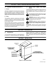
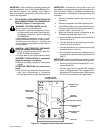
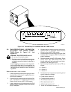
SECTION 3 – INSTALLATION
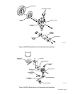
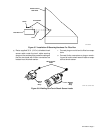
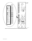
PAW Interface
Panel
Plug PLG21 Connects
To Computer Interface
Receptacle RC8
(See Section 3-7)
Receptacle RC20
(See Section 3-8)
Computer
Interface
Computer Interface
Input Power Receptacle RC11
Location (See Section 3-9 And
Computer Interface Owner’s Manual)
ST-800 732
Receptacle RC21
(See Section 3-8)
Gas Set/Pilot Arc
Start Push Button
Figure 3-1. PAW Interface Panel