


OM-169 510 Page 7
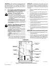
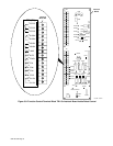
Robot Control
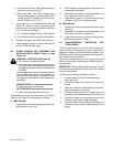
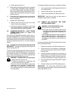
Side Panel
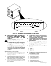
Filter Box
Cord
Screw
Star Washer
Nut
ST-152 641
Figure 3-7. Installation Of Securing Hardware For Filter Box
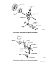
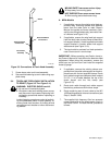
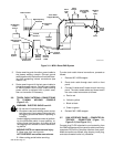
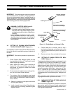
q. Route supplied 35 ft. (10.5 m) shielded shock
sensor cable under the torch cable securing
straps on the outside of the protective casing so
that the two leads with friction connectors are
located near the shock sensor.
r. Connect plug on end of cord to filter box recep-
tacle.
s. Connect friction connectors or plug on remain-
ing end of cord to shock sensor leads or recep-
tacle at shock sensor.
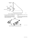
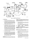
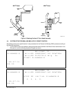
ST-141 731 / ST-137 518
Shock Sensor
Welding
Gun
Body
Welding
Gun
Body
Leads
Figure 3-8. Welding Gun/Torch Shock Sensor Leads