


OM-169 510 Page 10
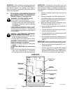
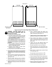
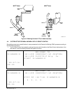
PAW/Computer
Torch Cable
Support Bracket
Ground
Rod No.2
Braided
Interface
Servo
Ground
Cable
Robot Control
High Frequency
Filter Box
Shock Sensor
Cable
Torch
Braided
Cable
115VAC Input
Power Cord
WC 100B
Plasma
Welding
Console
Torch Cable
In Protective
Case
Shock
Sensor
Cable
Light
Box
Ground
Cable
Coolant
System
DC Welding
Power
ST-800 735-A
Hanger
Source
Welding
Gun
Body
Ground
Rod No.1
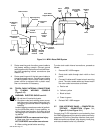
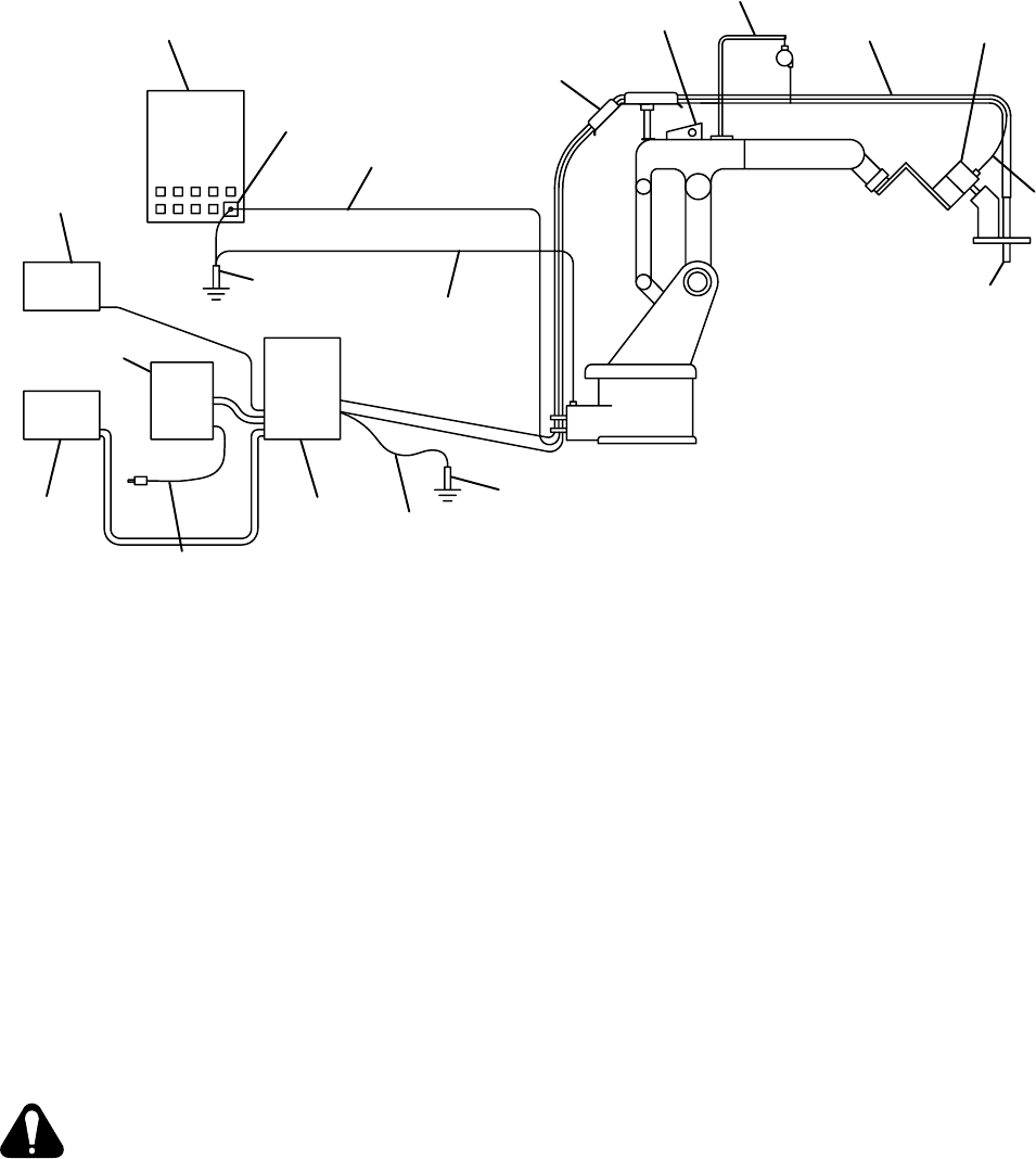
Figure 3-11. MRV
2
Robot PAW System
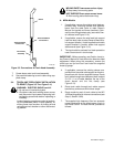
3. Route remaining end of another ground cable to
the plasma welding console. Connect ground
cable together with the lead from the shield sleev-
ing after completing internal connections (see
Section 3-8).
4. Route remaining end of the last ground cable to
the welding power source. Connect ground cable
to welding power source case unless welding
power source is equipped with a plastic case,
then no connection is necessary.
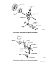
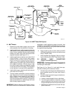
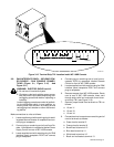
3-6. TORCH CABLE INTERNAL CONNECTIONS
TO PLASMA WELDING CONSOLE
(Figure 3-12)
WARNING: ELECTRIC SHOCK can kill.
•
Do not touch live electrical parts.
•
Shut down robot and welding power source,
and disconnect input power employing lock-
out/tagging procedures before inspecting or
installing.
Lockout/tagging procedures consist of padlock-
ing line disconnect switch in open position, re-
moving fuses from fuse box, or shutting off and
red-tagging circuit breaker or other disconnect-
ing device.
MOVING PARTS can cause serious injury.
•
Keep away from moving parts.
HOT SURFACES can cause severe burns.
•
Allow cooling period before servicing.
To make torch cable internal connections, proceed as
follows:
1. Remove WC 100B wrapper.
2. Route torch cable through strain relief on front
panel.
3. Connect 2 cables and 2 hoses to torch mounting
panel. The color-coded cables and hoses match
the color-coded connectors as follows:
a. Red to red
b. Yellow to yellow
c. Black to black
d. Green to green
4. Reinstall WC 100B wrapper.
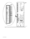
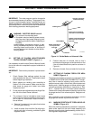
3-7. PAW INTERFACE PANEL – COMPUTER IN-
TERFACE CONNECTION (Figure 3-1,
Figure 3-10, And Figure 3-11)
Connect plug PLG21 attached to cord extending from
the PAW Interface panel front panel to weld current relay
receptacle RC8 on the Computer Interface front panel.
Make connections as follows: align keyway, insert plug,
and rotate threaded collar fully clockwise.