


OM-169 510 Page 4
g. Connect lead 23 from PAW interface panel to
terminal A on terminal strip 2T.
h. Route plug 30/31 from PAW interface panel
through center baffle in computer interface. Dis-
connect plug PLG10 from plug PLG11 and con-
nect PLG 30/31 to PLG 10/11.
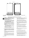
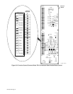
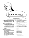
5. Locate switch S1 on Interface Board PC4 (see
Figure 3-2). Remove varnish and potting com-
pound from S1 and place the two DIP switches on
S1 in the following positions:
a. S1-1 (Disable Voltage Ramp) in OFF position.
b. S1-2 (Disable Stick Checking) in ON position.
6. Reinstall side panel onto PAW Interface panel.
7. Install supplied top cover onto the Computer In-
terface – PAW Interface panel.
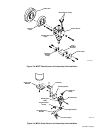
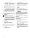
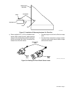
3-2. SHOCK SENSOR UNIT ASSEMBLY AND
INSTALLATION TO ROBOT (Figure 3-3 And
Figure 3-4)
WARNING: ELECTRIC SHOCK can kill.
•
Do not touch live electrical parts.
•
Shut down robot and welding power source,
and disconnect input power employing lock-
out/tagging procedures before inspecting or
installing.
Lockout/tagging procedures consist of padlock-
ing line disconnect switch in open position, re-
moving fuses from fuse box, or shutting off and
red-tagging circuit breaker or other disconnect-
ing device.
MOVING PARTS can cause serious injury.
•
Keep away from moving parts.
HOT SURFACES can cause severe burns.
•
Allow cooling period before servicing.
To assemble and install the shock sensor unit, refer to
Figure 3-3 or Figure 3-4 and proceed as follows:
A. MRH
2
Models
1. If applicable, remove existing gun/torch and insu-
lator plate from robot arm.
2. Install supplied insulator plate to robot arm with
screws removed in Step 1.
3. Assemble shock sensor, mounting bracket, and
torch clamp as shown in Figure 3-3.
4. Install shock sensor unit to the insulator plate
installed in Step 2 with supplied screws.
B. MRV
2
Models
1. If applicable, remove existing shock sensor from
robot arm.
2. Assemble shock sensor, mounting bracket, and
torch clamp as shown in Figure 3-4.
3. Install shock sensor unit to robot insulating block
with screws removed in Step 1.
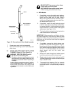
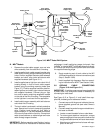
3-3. HIGH-FREQUENCY PROTECTION FOR
TORCH CABLE
The Pilot mode switch on the WC 100B console pro-
vides a selection for the pilot arc mode of operation. If
plasma arc welding is performed with the switch in the
NORMAL position, the optional shield sleeving should
be installed on the torch cable.
The optional shield sleeving is for covering the torch
cable to prevent high frequency from interfering with ro-
bot operations.
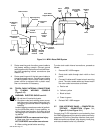
IMPORTANT:
When installing shield sleeving, be sure
end with lead and attached ring terminal is at console
end of the torch cable.
To install shield sleeving, proceed as follows:
1. Unscrew sleeve from torch head assembly
(see Figure 3-5).
2. Disconnect fittings and remove torch head as-
sembly.
3. Insert torch cable into shield sleeving at end with
lead and attached ring terminal.
4. Slide shield sleeving over torch cable until end of
torch cable exits opposite end of shield sleeving.
5. Reconnect fittings from torch cable to torch head
assembly (match color-coded markings).
6. Check for coolant leaks at fittings by turning on re-
circulating coolant system. Tighten fittings if nec-
essary.