


OM-169 510 Page 12
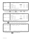
g. Yellow lead to terminal 14.
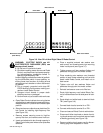
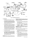
9. Route cable from welding power source negative
(–) weld output receptacle through opening in
rear of WC 100B console. Route end of cable to
shunt, located where torch cable bus bar is con-
nected, and connect cable to shunt at end oppo-
site from bus bar.
10. Route cable from welding power source positive
(+) weld output receptacle and connect end of
cable to workpiece.
11. Reinstall WC 100B wrapper.
a. Remove paint from around right front screw
hole on right side of wrapper,
b. Connect ring terminal, located on end of lead
from shield sleeving, to wrapper using screw
that secures right front side of wrapper.
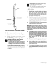
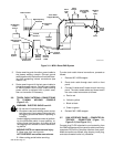
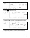
3-9. COMPUTER INTERFACE – INPUT POWER
CONNECTIONS (Figure 3-1, Figure 3-10,
And Figure 3-11)
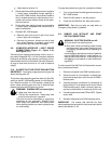
Connect plug on supplied input power cord to 14-pin in-
put power receptacle RC11 on the Computer Interface
front panel as follows: align keyway, insert plug, and ro-
tate threaded collar fully clockwise. Connect input pow-
er plug on other end of cord to a 115 volts ac external
supply.
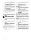
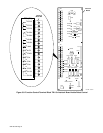
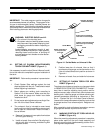
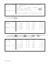
3-10. GAS SET/PILOT ARC START PUSH BUTTON
IMPORTANT:
Thoroughly purge plasma torch gas line
before starting pilot arc.
This button starts shielding gas flow when the Run/Set
switch on the WC 100B welding panel is in the Set posi-
tion. When the switch is in Run position, pressing the
button starts shielding gas flow and 5 seconds later
plasma gas flows and the pilot arc ignites.
WARNING: PLASMA ARC can cause injury.
•
Keep away from the torch tip.
•
Pilot arc can cause burns – keep away from
torch tip when pilot arc is present.
The pilot arc can be intermittent or continuous
depending on the application. ALWAYS point
torch away from personnel and toward work
when starting the pilot arc or leaving the pilot arc
on continuously.
To purge the plasma torch gas line, proceed as follows:
1. Turn on input power to welding power source and
WC 100B console.
2. Place Run/Set switch in the Set position.
3. Press the Gas Set/Pilot Arc Start push button.
IMPORTANT:
Gas flow and pilot arc stop when an
Emergency Stop button is pressed.
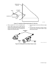
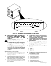
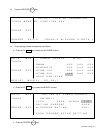
3-11. REMOTE GAS SET/PILOT ARC START
SWITCH CONNECTIONS
WARNING: ELECTRIC SHOCK can kill.
•
Do not touch live electrical parts.
•
Shut down robot and welding power source,
and disconnect input power employing lock-
out/tagging procedures before inspecting or
installing.
Lockout/tagging procedures consist of padlock-
ing line disconnect switch in open position, re-
moving fuses from fuse box, or shutting off and
red-tagging circuit breaker or other disconnect-
ing device.
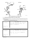
To make remote Gas Set/Pilot Arc Start switch connec-
tions, proceed as follows:
1. Remove side panel from PAW Interface panel.
2. Route one end of a 2-conductor, customer-sup-
plied cord through strain relief on rear of PAW In-
terface panel.
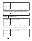
3. Installing terminal connectors for connecting to
terminal strip 6T onto leads at end of cord inside
PAW Interface panel. Install a normally open mo-
mentary contact switch to remaining end of cord.
4. Connect leads to terminals 6TB and 6TD. Tighten
strain relief.
5. Reinstall side panel onto PAW Interface panel.
IMPORTANT:
The remote Gas Set/Pilot Arc Start
switch operates the same as the front panel push button
switch (see Section 3-10).