


OM-169 510 Page 11
ST-800 736
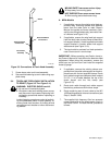
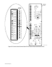
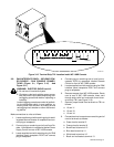
1 2 3 4 5 6 7 8 9 10 11 12 13 14 15
C
O
N
T.
PILOT PILOT
PLASMA
SHIELD
1CR CSR PSR
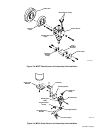
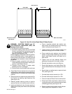
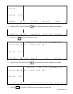
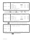
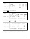
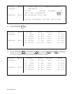
Figure 3-12. Terminal Strip TB1 Location Inside WC 100B Console
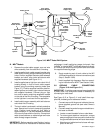
3-8. PAW INTERFACE PANEL – WELDING POW-
ER SOURCE – PAW CONSOLE CONNEC-
TIONS (Figure 3-1, Figure 3-10, And
Figure 3-11)
WARNING: ELECTRIC SHOCK can kill.
•
Do not touch live electrical parts.
•
Shut down robot and welding power source,
and disconnect input power employing lock-
out/tagging procedures before inspecting or
installing.
Lockout/tagging procedures consist of padlock-
ing line disconnect switch in open position, re-
moving fuses from fuse box, or shutting off and
red-tagging circuit breaker or other disconnect-
ing device.
Make connections to units as follows:
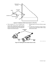
1. Locate supplied cord with matching plug for weld-
ing power source Remote 14 receptacle and con-
nect plug to receptacle.
2. Connect plug on remaining end of cord from Re-
mote 14 receptacle to receptacle labeled Power
Supply Control on rear of WC 100B console.
3. Locate supplied cord with matching plug for PAW
interface panel receptacle RC20 and connect
plug to receptacle.
4. Connect plug on remaining end of cord from re-
ceptacle RC20 to receptacle labeled Remote
Control on front of WC 100B console.
5. Locate supplied cord with matching plug for PAW
interface panel receptacle RC21 and connect
plug to receptacle.
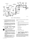
6. Remove wrapper from WC 100B console. Route
cord to rear of WC 100B console. Insert cord
through strain relief and route end of cord to ter-
minal strip TB1 (see Figure 3-12).
7. Remove jumper leads from terminals on TB1 as
follows:
a. 10 and 11
b. 12 and 13
c. 13 and 14
8. Connect terminal connectors on remaining end of
cord to terminals as follows:
a. Green lead to terminal 5
b. Orange lead to terminal 6
c. Brown lead to terminal 10
d. Blue lead to terminal 11
e. White lead to terminal 12
f. Black and red leads to terminal 13