


4 Connection
MITSUBISHI CNC
96
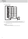
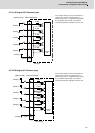
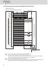
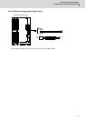
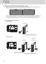
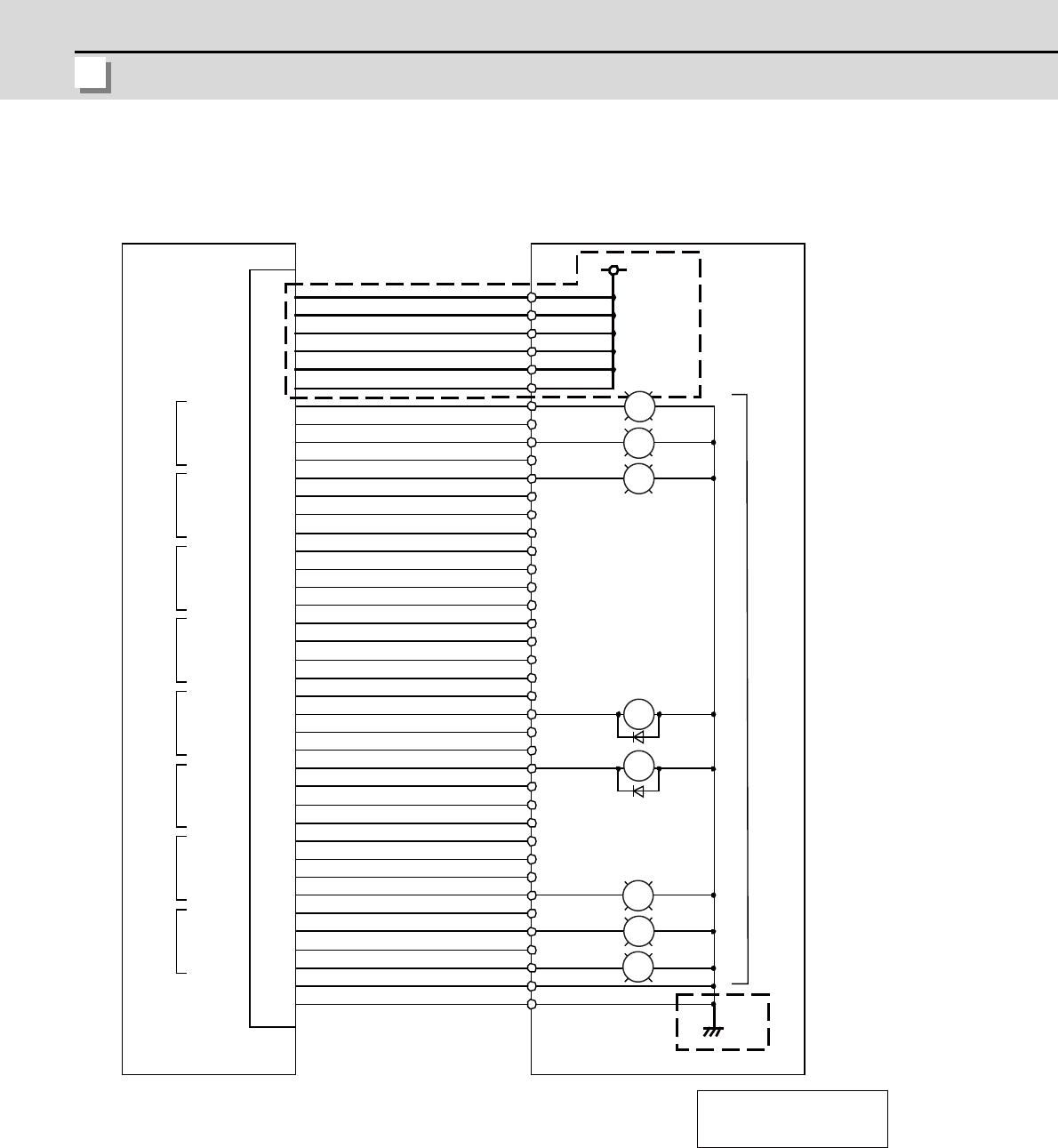
4.3.4.3 Wiring for Source Type Output (FCU7-DX621/DX711/DX721/DX731)
(Note 1) Connect +24V to either or both of the flat connector 1B, 2B (24VDC). (*1)
(Note 2) Connect +24V (GND) to the flat connector 3A, 3B, 4A, 4B (24VDC). (*1)
Decide the number of 24VDCs to wire with regard to the total amount of each connector's maximum output
current and the voltage drop by the cables. The rated current is 1A per connector pin.
(Note 3) Connect 0V (GND) to the flat connector 1A, 2A (GND). (*2)
(Note 4) When large current flows due to small amount of connected load, fuse may be blown out or 24V power supply
voltage may drop. In order to secure the appropriate current value, watch the connected load.
2B
20B
19B
18B
17B
16B
15B
14B
13B
12B
11B
10B
9B
8B
7B
6B
5B
CG32 (CG34,CG36)
3A
3B
GND
1A
2AGND
1B
4A
4B
GND
࣭
࣭
࣭
࣭
࣭
࣭
࣭
࣭
࣭
࣭
࣭
Y200
Y201
Y202
Y203
Y204
Y205
Y206
Y207
Y208
Y209
Y20A
Y20B
Y20C
Y20D
Y20E
Y20F
Y210
Y211
Y212
Y213
Y214
Y215
Y216
Y217
Y218
Y219
Y21A
Y21B
Y21C
Y21D
Y21E
Y21F
20A
19A
18A
17A
16A
15A
14A
13A
12A
11A
10A
9A
8A
7A
6A
5A
PL
PL
PL
RA
RA
PL
PL
PL
RA
PL
:
:
Relay
Pilot lamp
24VDC
24VDC
24VDC
24VDC
24VDC
24VDC
Operation panel I/O unit
(Card name : HN331/HN351/HN371/HN372)
Machine side
*1 Additional wiring
*2 Additional wiring
Output device (Connection example)
24VDC