


2 General Specifications
MITSUBISHI CNC
38
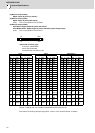
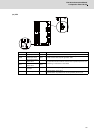
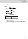
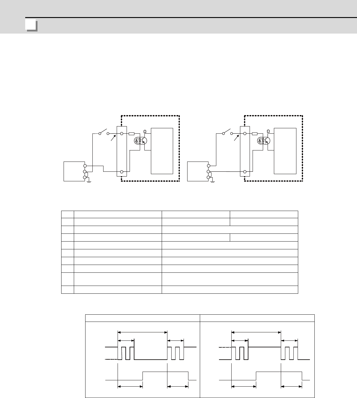
(1) Machine input (DI-L)
(2) Machine input (DI-R)
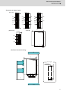
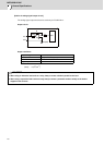
Both 24V common and 0V common connections are allowed in the digital signal input circuit.
Follow the wiring diagram below for each type.
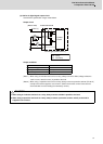
Input circuit
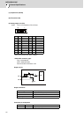
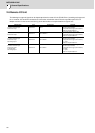
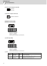
Input conditions
The input signals must be used within the following condition ranges.
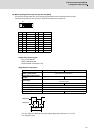
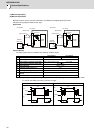
(Note) Input signal holding time: The guide is 40ms or more. The input signal will not be recognized unless
it is held for the ladder processing cycle time or longer.
(E) : External signal, (I) : Internal signal
24V common 0V common
1 Input voltage at external contact ON 6V or less 18V or more, 25.2V or less
2 Input current at external contact ON 9mA or more
3 Input voltage at external contact OFF 20V or more, 25.2V or less 4V or less
4 Input current at external contact OFF 2mA or less
5 Input resistance Approx. 2.2kΩ
6 Tolerable chattering time (T1) 3ms
7 Input signal holding time (T2) 40ms or more (Note)
8
input circuit operation delay time (T3
and T4)
3 to 16ms
9 Machine side contact capacity 30V or more, 16mA or more
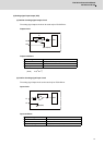
Connection to 24V common input Connection to 0V common input
A3,B3
A3,B3
R
0V
FG
COM
0V
FG
COM
R
DI-L / DI-R
2.2k
DI-L / DI-R
2.2k
24VDC(+)
Control
circuit
(Machine side)
Stabilized
power supply
External contact
Input voltage
Input resistor
24VDC(+)
Input voltage
24V common
0V common
Control
circuit
(Machine side)
Stabilized
power supply
External contact
Input resistor
T1T1
T2
GND
+24V
T4T3
(E)
(I)
T1T1
T2
T4T3
GND
+24V
(E)
(I)