


3 Installation
MITSUBISHI CNC
62
3.1 Heat Radiation Countermeasures
Please refer to the following method for heat radiation countermeasures.
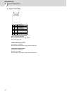
Example of heat radiation countermeasures
<Hypothetical conditions>
(1) Average internal temperature of operation panel: T ≤ 55°C
(2) Peripheral temperature of operation panel : Ta ≤ 0°C to 45°C
(3) Internal temperature rise value : ΔT = T - Ta (max) = 10°C
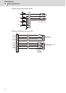
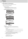
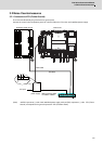
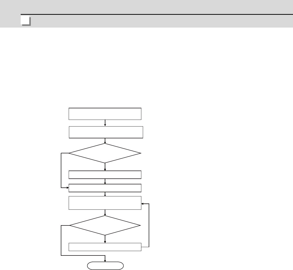
Procedures for heat design and verification
<Supplement>
(1) Refer to "General Specification" for the heat generated by each unit.
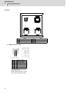
(2) Enclosed cabinet (thin steel plate) cooling capacity calculation equation
W1 = U × A × ΔT
U: 6 W/m
2
°C
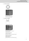
A: Effective heat radiation area (m
2
) (Area where heat can be radiated from operation panel)
ΔT: Internal temperature rise value (10°C)
(Caution) 8 W/m
2
°C can be applied only when the operation panel is so small that the internal
temperature stays uniform.
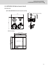
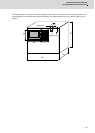
(3) Points of caution for heat radiation countermeasures when designing mounting state
- Consider convection in operation panel (eliminate heat spots)
- Collect hot air at suction port of heat exchanger in operation panel.
(4) Criterion for internal temperature rise distribution data
ΔT (average value) ≤ 10°C
ΔTmax (maximum value) ≤ 15°C
R (inconsistency ΔTmax - ΔTmin) ≤ 6°C
(Evaluate existence of heat spots)
W
≤
W1
W>W1
ΔT
≤
10°C
ΔT>10°C
Calculate total heat radiation of each
mounted unit (W)
Comparison of W and W1
Collection of internal temperature rise
distribution data
Mounting design
Improvements
Completion
Selection of heat exchanger
Evaluation
Calculate cooling capacity of
operation panel (W1)