


Appendix 2 EMC Installation Guidelines
MITSUBISHI CNC
168
Appendix 2.6 EMC Countermeasure Parts
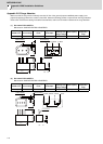
Appendix 2.6.1 Shield Clamp Fitting
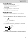
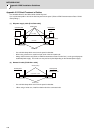
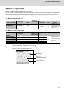
The effect can be improved by directly connecting the cable's shield sheath to the grounding plate as shown below.
Install the grounding plate near the outlet (within 10cm) of each panel, and press against the grounding plate with the
clamp fitting.
If the cables are thin, several can be bundled and clamped together.
To provide sufficient frame ground, install the grounding plate directly on the cabinet or connect with a grounding wire.
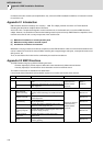
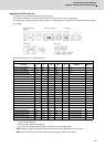
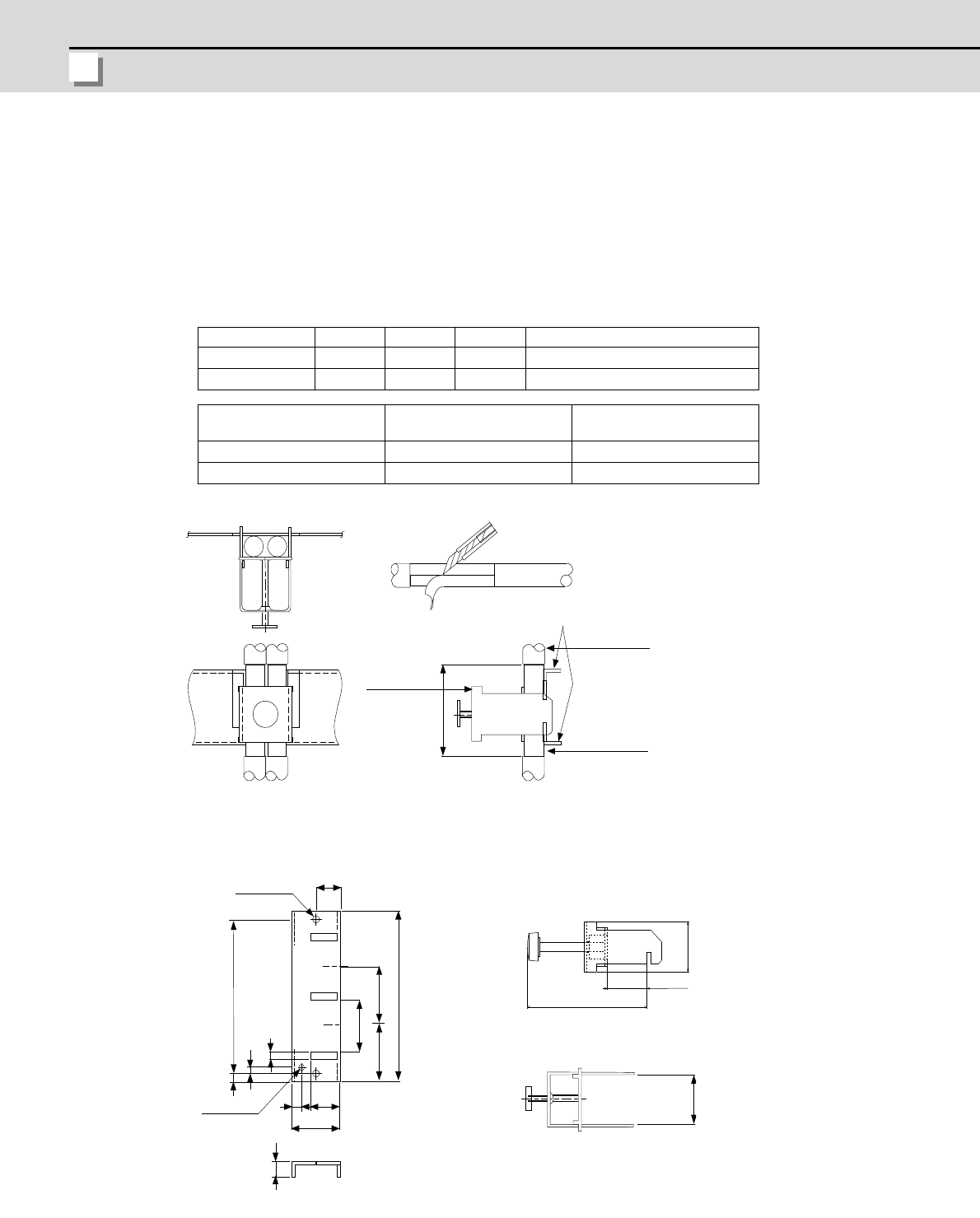
A B C Enclosed fittings
Ground Plate #D 100 86 30 Clamp fitting A×2
Ground Plate #E 70 56 - Clamp fitting B×1
L1 (maximum dimension
when it is open)
L2 (reference dimension)
Clamp fitting A 25 (77)
Clamp fitting B 12 (54)
+
0
.
3
0
2
4
4
0
35
6
22
17.5
A
C
3
5
2
4
-
0
.
2
0
1
1
7
3
6
B
r
0
.
3
30
2- Ǿ
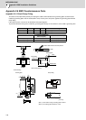
[Unit: mm]
(Note 1) Screw hole for wiring to earthing plate in cabinet.
(Note 2) The earthing plate thickness is 1.6mm.
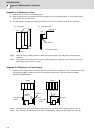
hole
(Fitting A, B)
Installation hole
Clamp fittingEarthing plate
Outline drawing
5
M4 screw
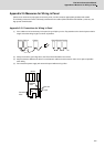
0QVG
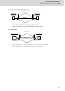
Shield sheath
Cable
Cable
Earthing plate
Peel the cable sheath at the clamp section.
View of clamp section
Clamp fitting