


1 System Configuration
MITSUBISHI CNC
2
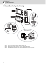
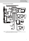
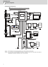
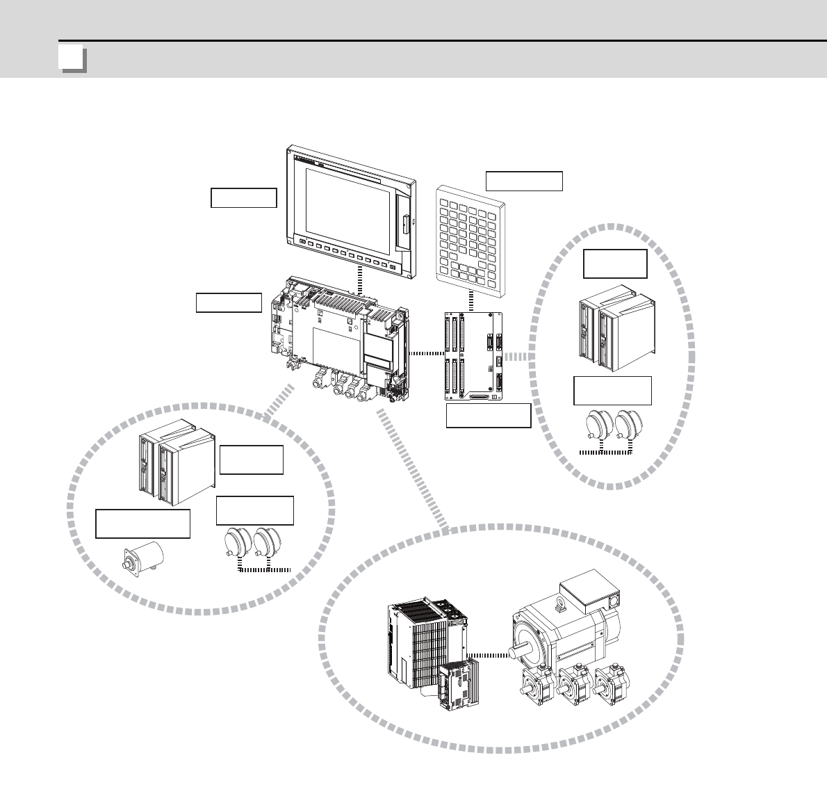
1.1 System Basic Configuration Drawing
(Note 1) Control unit is mounted on the back side of the display unit.
(Note 2) Operation panel I/O unit is mounted on the back side of the keyboard unit.
(Note 3) For the drive unit configuration, refer to the Instruction Manual of the drive unit you use.
Display unit
Keyboard unit
Operation panel
I/O unit
Control unit
Manual pulse
generator
Servo/Spindle drive units
Motors
Synchronous feed
encoder
Remote I/O
unit
Manual pulse
generator
Remote I/O
unit