


Contents
1 System Configuration.................................................................................................................................. 1
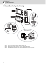
1.1 System Basic Configuration Drawing..................................................................................................... 2
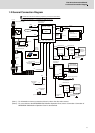
1.2 General Connection Diagram ................................................................................................................ 3
1.3 List of Configuration............................................................................................................................... 5
1.3.1 List of Units .................................................................................................................................... 5
1.3.2 Durable Parts................................................................................................................................. 6
1.3.3 Replacements................................................................................................................................ 6
1.3.4 List of Cables ................................................................................................................................. 7
2 General Specifications ................................................................................................................................ 9
2.1 Environment Conditions....................................................................................................................... 10
2.2 Control Unit.......................................................................................................................................... 11
2.3 Display Unit.......................................................................................................................................... 21
2.4 Keyboard Unit ...................................................................................................................................... 22
2.5 Operation Panel I/O Unit...................................................................................................................... 24
2.6 Remote I/O Unit ................................................................................................................................... 36
2.7 External Power Supply Unit ................................................................................................................. 43
2.8 Manual Pulse Generator...................................................................................................................... 45
2.9 Synchronous Feed Encoder ................................................................................................................ 47
2.10 MITSUBISHI CNC Machine Operation Panel.................................................................................... 48
2.10.1 MITSUBISHI CNC Machine Operation Panel A......................................................................... 48
2.10.2 MITSUBISHI CNC Machine Operation Panel B......................................................................... 55
2.11 Exclusive CF Cards for MITSUBISHI CNC........................................................................................ 59
2.11.1 Precautions for Use of Commercially Available CF Cards......................................................... 59
3 Installation .................................................................................................................................................. 61
3.1 Heat Radiation Countermeasures........................................................................................................ 62
3.2 Noise Countermeasures ...................................................................................................................... 65
3.2.1 Connection of FG (Frame Ground).............................................................................................. 65
3.2.2 Shield Clamping of Cables........................................................................................................... 66
3.2.3 Connecting Spark Killers.............................................................................................................. 66
3.3 Unit Installation .................................................................................................................................... 67
3.3.1 Display Unit.................................................................................................................................. 67
3.3.2 Keyboard Unit .............................................................................................................................. 68
3.3.3 Operation Panel I/O Unit.............................................................................................................. 68
3.3.4 Control Unit Battery...................................................................................................................... 69
4 Connection ................................................................................................................................................. 71
4.1 Precautions for Wiring.......................................................................................................................... 72
4.1.1 Precautions when Connecting/Disconnecting Cables ................................................................. 72
4.1.2 Precautions for Using Optical Communication Cable.................................................................. 75
4.1.2.1 Optical Communication Cable Outline and Parts ................................................................ 75
4.1.2.2 Precautions for Handling Optical Communication Cable..................................................... 75
4.1.2.3 Precautions for Laying Optical Communication Cable ........................................................ 76
4.1.3 Precautions for Connecting 24V Power Supply........................................................................... 76
4.2 Connection of Control Unit................................................................................................................... 77
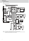
4.2.1 Control Unit Connection System Drawing....................................................................................77
4.2.2 Connecting with Power Supply.................................................................................................... 78
4.2.3 Connecting with Emergency Stop Signal.....................................................................................79
4.2.4 Connecting with Operation Panel I/O Unit ................................................................................... 81
4.2.5 Connecting with Drive Unit........................................................................................................... 82
4.2.5.1 Connecting with MDS-DM2 Series ...................................................................................... 83
4.2.5.2 Connecting with MDS-DJ Series ......................................................................................... 84
4.2.6 Connecting with RS-232C Device...........................................................................................
..... 85
4.2.7
Connecting with Skip Signal (Sensor).......................................................................................... 87
4.2.8 Connecting with Synchronous Feed Encoder/ Manual Pulse Generator..................................... 89
4.2.8.1 Handle Numbers.................................................................................................................. 89
4.2.9 Connecting with Safety Observing I/O Device............................................................................. 90