


2 General Specifications
MITSUBISHI CNC
52
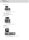
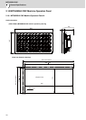
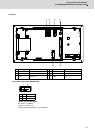
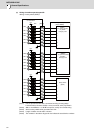
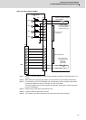
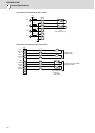
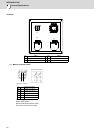
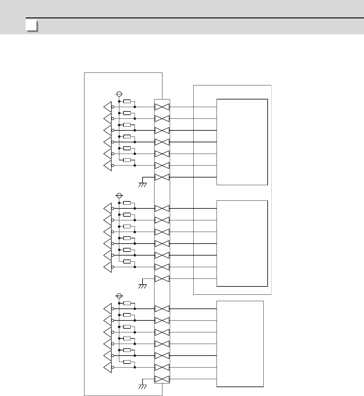
(a) Wiring of machine operation panel B
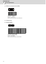
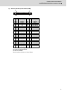
<Wiring of rotary switch (SUBP)>
(Note1) Use the special lead wire with a connector for wiring of rotary switch.
Lead wire with a connector: ACX011-705 (7 terminals, 0.5m) Fuji Electric
(Note2) A09 to 12 and B09 to 11 of SUBP are spares, so they do not need wiring.
(Note3) Select a rotary switch which guarantees 5V/1mA.
(Note4) Length of cables must be 0.5m or shorter.
(Note5) The numbers in the above diagram do not indicate the actual device numbers.
D
G
C
E
B
F
A
[SUBP]
X60
X61
X62
X63
X64
X65
X66
X67
X68
X69
X6A
X6B
B02
A01
B03
B01
A03
A02
A04
+5V
D
G
C
E
B
F
A
B06
A05
B07
B05
A07
A06
A08
+5V
(RSW2)
X6D
X6E
X6F
X70
X71
D
G
C
E
B
F
A
B10
A09
B11
B09
A11
A10
A12
+5V
1kΩ
X6C
R
R
R
R
R
R
R
R
R
R
R
R
R
R
R
R
R
R
21 position
(RSW1)
Machine Operation Panel
I/F PCB HN232
Machine operation panel B
(FCU7-KB926)
Rotary Switch
Real gray code
(For cutting override)
Rotary Switch
(For spindle override)
8 position
Real gray code
Rotary Switch
(Spare)