


E70 Series Connection Manual
2.10 MITSUBISHI CNC Machine Operation Panel
53
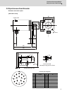
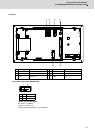
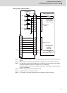
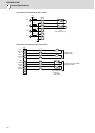
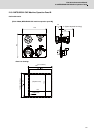
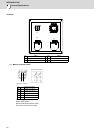
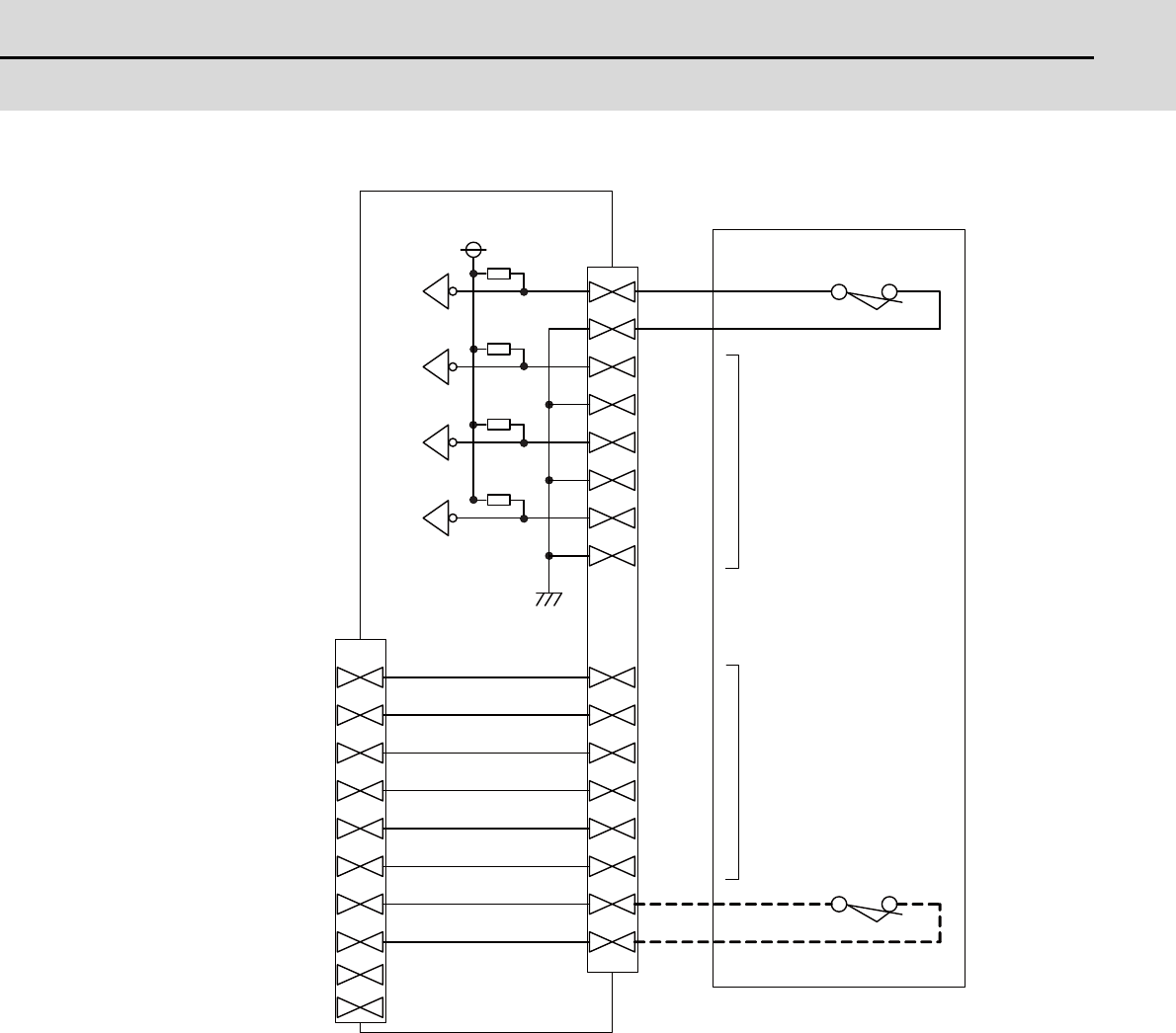
<Wiring of other switches (SUBP)>
(Note1) Wirings for selector switches must be directly soldered to terminals or use tab terminals (110
series).
(Note2) When wiring the emergency stop switch, the crimp terminal must be fastened with thread.
(Note3) For NCs whose control unit and display unit are integrated, wire the emergency stop switch
directly to the EMG connector of the control unit. (Use F120 cable)
And for NCs whose control unit and display are separated, relay it by the machine operation
panel I/F PCB HN232.
(Note4) Select a rotary switch which guarantees 5V/1mA.
(Note5) Length of cables must be 0.5m or shorter.
(Note6) The numbers in the above diagram do not indicate the actual device numbers.
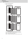
[SUBP]
X72
X73
X74
X75
B13
A13
A14
A15
A16
B20
A20
B14
B15
B16
+5V
[EXT]
A17
B17
A18
B18
A19
B19
EMG
B04
A04
B01
A01
B02
A02
B03
A03
1kΩ
A05
B05
R
R
R
R
Machine Operation Panel
I/F PCB HN232
Machine operation panel B
(FCU7-KB926)
Selector Switch
(For memory protection)
2 notch Key shape
2c Manual return type
Switch input spare
(3 points)
Push down switch
(For emergency stop)
Push Lock -
Turn Reset
2a2b contact
Spare for signal relay