


E70 Series Connection Manual
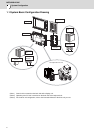
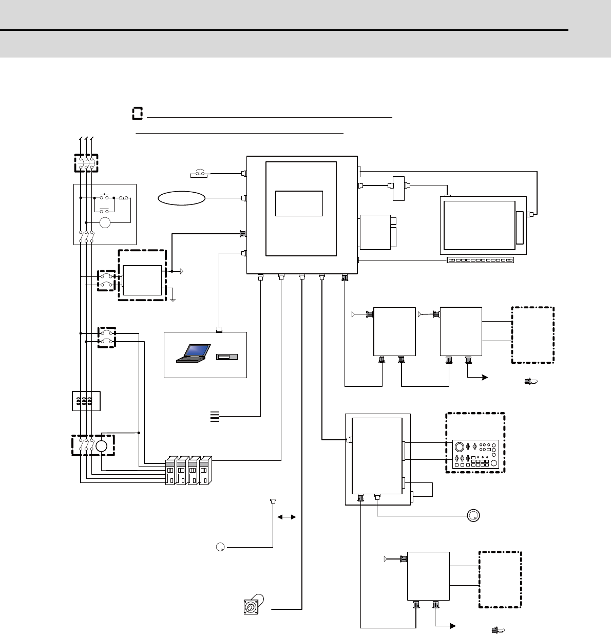
1.2 General Connection Diagram
3
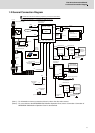
1.2 General Connection Diagram
(Note 1) For information on how to connect the drive unit, refer to the drive unit's manual.
(Note 2) For a connection of the MITSUBISHI CNC Machine Operation Panel, refer to "Connection: Connection of
MITSUBISHI CNC Machine Operation Panel" to be described.
L1 L2 L3
FCU7-KB0xx
FG
RIO2
EMG
SIO
NCKB
LCD
LED driver : HN281
1ch:F034
Sensor signals
Max.8points
LAN
CG3x
EMG
(VGA:640×480)
RIO1
OPT
FRONT
FCU7-DX621/7x1
DCIN
FCUA-DX1x1
RIO1
SKIP ENC
USER 2ch
2ch
1ch
INV
F120
12V:F320/F321
5V:F023/F024
FCUA-R030
G395/G396/G380
FCUA-R050/054
FCU7-DU120-13
G011
RIO2RIO1
DCIN
FCUA-DX1x1
CG71
DC24V DC24V
MENUKEY
2ch:F035
1ch
FCUA-R211
/SH41
CG71
HN441
max.0.5m
G300/G301
<G402>
RIO3 MPG
DI-L/R
RIO2RIO1
DCIN
FCUA-DX1x1
DC24V
FCUA-R211
/SH41
FCUA-R211
/SH41
F351
DI-L/R
FCUA-
R300
/R301
FCUA-
R300
/R301
F070
F070
F070
<G487>
D-AL
MC
ON OFF
MC
MC
MC
DCOUT
FG
ACIN
DC24V
DCIN
F070
CP/NFB
CP/NFB
HN793
CF card I/F
<G497>
FCU7-MU558
<G488>
OSE1024
USB
2ch
ENC
5V:G023/G024
The name with brackets < > indicates the cable for the unit.
Dotted lines indicate the sections prepared by the machine tool builder.
No-fuse breaker (NFB)
24VDC stabilized
power supply
Circuit protector (CP)
AC reactor
RS232C device
Contactor
Skip signal input
Drive units
Manual pulse
generator
Synchronous feed encoder
CNC control unit
Main card HN768
Memory card
Front
memory
I/F card
Display unit
Menu keys
Remote I/O unit Remote I/O unit
Machine
control relay/
contact
To the next remote I/O
or terminator
Machine operation
panel made by
machine tool builder
Keyboard unit
Operation panel I/O unit
Manual pulse generator
Remote I/O unit
To the next remote I/O
or terminator
Machine
control relay/
contact
Ethernet device
Select