


E70 Series Connection Manual
2.5 Operation Panel I/O Unit
31
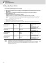
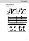
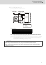
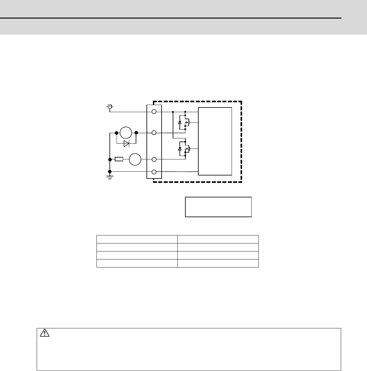
(a) Outline of digital signal output circuit
Use within the specification ranges shown below.
Output circuit
Output conditions
(Note 1) When using an inductive load such as a relay, always connect a diode (voltage resistance
100V or more, 100mA or more) in parallel to the load.
(Note 2) When using a capacitive load such as a lamp, always connect a protective resistor (R=150Ω)
serially to the load to suppress rush currents. (Make sure that the current is less than the
above tolerable current including the momentary current.)
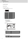
Insulation method Insulation
Rated load voltage 24VDC
Max. output current 60mA/point
Output delay time 40μs
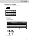
CAUTION
1. When using an inductive load such as a relay, always connect a diode in parallel to the load.
2. When using a capacitive load such as a lamp, always connect a protective resistor serially to the load to
suppress rush currents.
R
RA
CG32/CG34/CG36
PL
RA
PL
24VDC(+)
Source type (DX621/DX7x1)
Control
Circuit
(Macine side)
: Relay
: Pilot lamp