


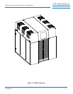


9600 Compressor Installation, Operation, and Maintenance
P/N 8040540 1-11
C
HELIX TECHNOLOGY CORPORATION
-
TI C
RY
OG
EN
ICS
Cryopump Power Phase Switch
NOTE: The Cryopump Power Phase Switch is behind the system circuit
breaker cover.
The Cryopump Power Phase Switch matches the output power phase of the
9600 compressor to that of the cryopump. The switch is set to the two or
three phase position based upon cryopump power requirements. Refer to
Section 3 - Installation for more information.
Compressor Remote Connector
The Compressor Remote Connector is a two-pin connector that can be used
in conjunction with the On-Board setpoint relays, relays in the Cryo-Torr
Interface, or a signal from the vacuum system to turn the Compressor ON
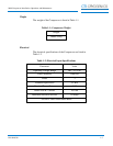
or OFF. Refer to Table 1-6 for connector pin identification. Switching
contacts must be rated at 24VDC, 2.7A inductive.
NOTE: The Compressor is shipped with a mating plug which must remain
installed in the Compressor Remote Connector to ensure Compressor
operation when the Compressor remote feature is not being used.
Supply Gas Coupling
The Supply Gas Coupling provides a connection for high pressure
compressed helium to the cryopump cold head. Refer to
CTI-CRYOGENICS Helium Refrigeration System within this section
for more information.
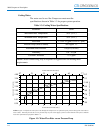
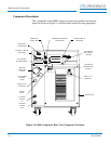
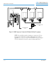
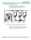
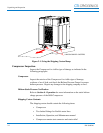
Multiple On-Board Cryopump Connections
The On-Board Splitter Box permits the connection of multiple On-Board
Cryopumps or Waterpumps to one 9600 Compressor as shown in Figure
1-5. Refer to Section 3 - Installation for more information on connecting
single or multiple On-Board Cryopumps or Waterpumps to the
Compressor.
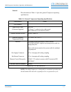
Table 1-6: Compressor Remote Connector Pin Assignments
Identifier Function
A and B Compressor Remote Control - Make = ON, Break = OFF