


Installation
3-14 P/N 8040540
C
HELIX TECHNOLOGY CORPORATION
-
TI C
RY
OG
EN
ICS
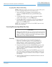
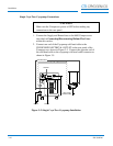
1. Connect the Supply and Return lines to the 9600 Compressor as
described in Connecting/Disconnecting Helium Flex Lines
within this section.
2. Connect the Gas Return Line to the customer supplied helium
manifold and then to the Gas Return connector on the Cryo-Torr
Cryopump.
3. Connect the Gas Supply Line to the customer supplied helium
manifold and then to the Gas Supply connector on the Cryo-Torr
Cryopump.
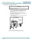
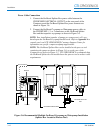
Power Cable Connections
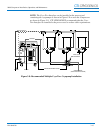
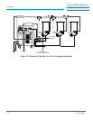
1. Connect the Cryo-Torr power cable between the CRYOPUMP
ELECTRICAL OUTLET on the rear panel of the Compressor
and the CRYOPUMP ELECTRICAL INPUT on the Cryo-Torr
Interface as shown in Figures 3-8 or 3-9.
2. Connect the Cryo-Torr Power Cables between the CRYOPUMP 1,
2, or 3 connectors on the Cryo-Torr Interface and the respective
Cryo-Torr Cryopumps as shown in Figures 3-8 or 3-9.
3. Connect the User Remote cable to the Cryo-Torr Interface as shown
in Figures 3-8 or 3-9.
4. Connect the Remote cable between the Cryo-Torr Interface and the
Compressor as shown in Figures 3-8 or 3-9.
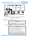
NOTE: Your installation may vary based upon the Cryo-Torr Cryopump
models used. Refer to Appendix A to consult your local
CTI-CRYOGENICS Customer Support Center for information on specific
compressor/cryopump applications.