


9600 Compressor Installation, Operation, and Maintenance
P/N 8040540 3-5
C
HELIX TECHNOLOGY CORPORATION
-
TI C
RY
OG
EN
ICS
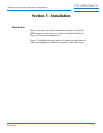
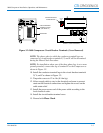
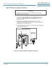
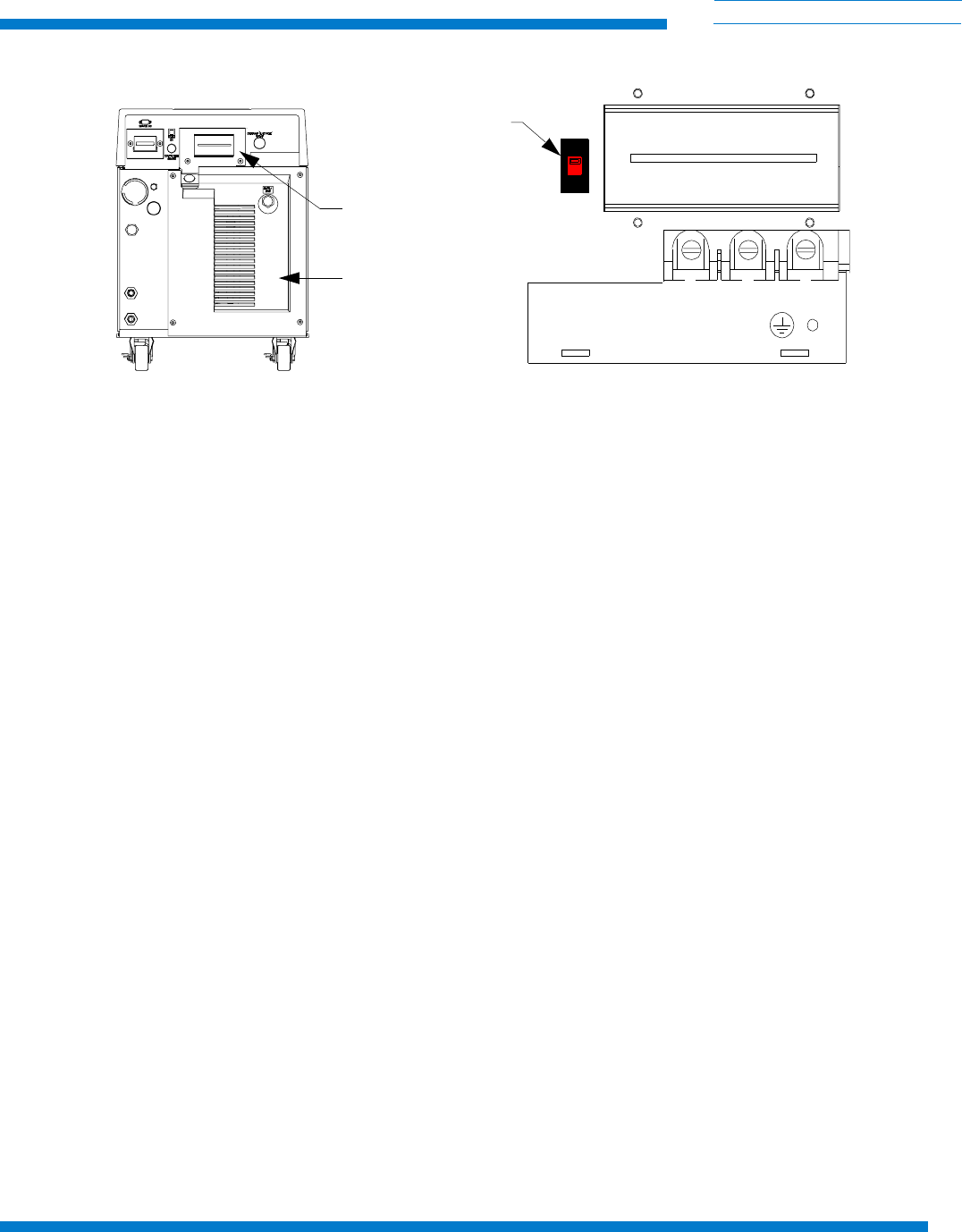
Figure 3-2: 9600 Compressor Circuit Breaker Terminals (Cover Removed)
NOTE: The phase order in which the conductor terminal lugs are
connected to circuit breaker terminals X, Y, and Z will be determined
during the Phase Check Procedure.
NOTE: For installation where one of the three phase legs is at or near
ground potential, connect that leg to terminal Y on the Compressor as
shown in Figure 3-2.
10. Install the conductor terminal lugs to the circuit breaker terminals
X, Y, and Z as shown in Figure 3-2.
11. Torque the screws to 12 in.-lbs (0.14m-kg).
12. Allow enough cable to stay in the electrical enclosure to prevent
strain on the electrical connections and tighten the screws on the
cable strain relief.
13. Install the power source end of the power cable according to the
local electrical codes.
14. Install the circuit breaker terminal cover.
15. Proceed with Phase Check.
(SEE DETAIL A)
REAR PANEL
CIRCUIT BREAKER
TERMINAL COVER
X
Y
Z
DETAIL A (COVER REMOVED)
THREE PHASE POWER
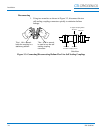
CRYOPUMP
PHASE
2Ø
3Ø
CRYOPUMP MOTOR
PHASE SWITCH