


Installation
3-4 P/N 8040540
C
HELIX TECHNOLOGY CORPORATION
-
TI C
RY
OG
EN
ICS
Electrical Connections
The following procedures provide information for making all three phase
(180 - 250 VAC) electrical connections to the Compressor.
Power Cable Preparation
WARNING
Follow all local high voltage safety precautions when performing this
procedure to reduce the possibility of electrical shock. Make sure all
electrical power is OFF before proceeding with this procedure.
CAUTION
The cable used for making the Compressor power cable must be 10
gauge, 3 conductor cable with ground rated at 600 VAC.
1. Cut a 10 AWG (6.00 mm
2
), 3 conductor cable with ground to an
appropriate length.
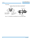
2. Strip the cable jacket back 4 in. (101.6 mm).
3. Strip the insulation back 3/8 in. (9.3 mm) on each individual
conductor.
4. Install a #10 ring tongue terminal on the end of each conductor
using the appropriate size double crimping tool.
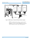
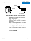
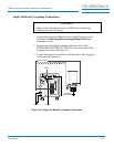
5. Remove the rear panel as shown in Figure 3-2.
6. Remove the circuit breaker terminal cover as shown in Figure 3-2.
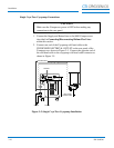
7. Install the cable into the Compressor through the cable strain relief.
8. Remove the 10-32 nut and install the grounding wire on the ground
stud. Install the nut and tighten to 18 in.-lbs (0.21m-kg).
NOTE: Use a slotted screwdriver which is capable of holding a screw
when performing steps 9 and 10.
9. Remove the screws from the Compressor circuit breaker terminals
X, Y, and Z as shown in Figure 3-2.