


9600 Compressor Installation, Operation, and Maintenance
P/N 8040540 3-7
C
HELIX TECHNOLOGY CORPORATION
-
TI C
RY
OG
EN
ICS
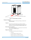
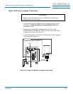
Cryopump Power Phase Switch Setting
NOTE: On-Board Cryopumps can operate on two or three-phase power.
Cryo-Torr Cryopumps only operate on two-phase power.
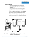
1. Inspect the On-Board Cryopump(s) being installed for the
presence of a THREE-PHASE label by the RETURN helium
connector.
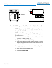
2. If a three-phase label is present, set the cryopump power phase
switch, shown in Figure 3-2, to the 3PH position.
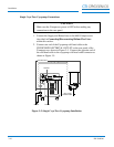
3. If a three-phase label is not present, or Cryo-Torr Cryopumps are
being installed, set the cryopump power phase switch, shown in
Figure 3-2, to the 2PH position.
NOTE: All Cryopumps being connected to the 9600 Compressor must
operate at the same phase.
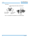
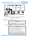
Connecting/Disconnecting Helium Flex Lines
CAUTION
Make sure the helium flex lines are connected and disconnected from
the 9600 Compressor using the following procedure and as shown in
Figure 3-3. Failure to follow this procedure could damage connector
O-ring seals or cause a helium circuit leak.
Connecting
1. Remove all dust plugs and caps from the Gas Supply and
Return lines, and the Compressor and cryopump Supply and
Return connectors. Check for the presence of a flat gasket in
the male connector, and no gasket in the female connector.
2. Connect the Gas Return line to the GAS RETURN connector on the
rear of the Compressor and then to the GAS RETURN connector
on the cryopump. Using two wrenches as shown in Figure 3-3,
tighten the connector.
3. Connect the Gas Supply line to the GAS SUPPLY connector on the
rear of the Compressor and then to the GAS SUPPLY connector on
the cryopump. Using two wrenches as shown in Figure 3-3, tighten
the connector.
4. Attach the Supply and Return line identification labels to each end
of the appropriate lines.