


12
Adjustments
Disconnect jointer from
power supply before making adjustments.
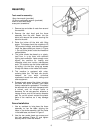
Drive Belt Tension
To check the tension of the drive belts:
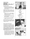
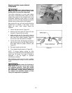
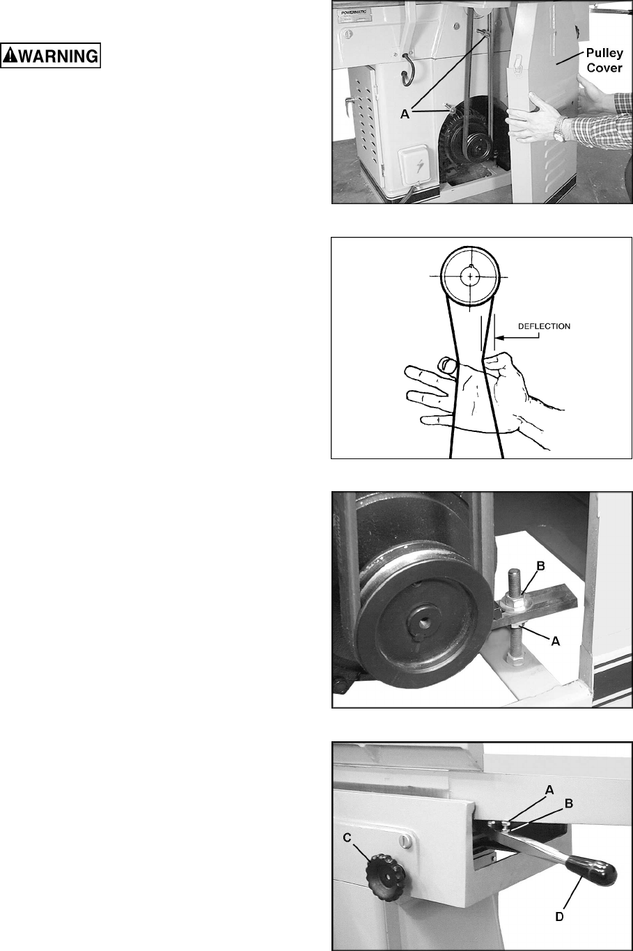
1. Remove the three cap nuts and flat washers
on the pulley cover with a 9/16 wrench, and
remove the guard to expose the belts and
pulleys. See Figure 9.
NOTE: The hex nuts and flat washers on the
threaded rods (A, Figure 9) should be left in
place; they keep the pulley cover from bending
as it is being tightened back into place with the
cap nuts.
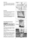
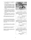
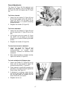
2. There should be a small amount of
deflection in the belt when pressing it
midway between the pulleys with moderate
finger pressure (Figure 10).
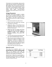
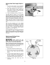
3. If the belts need tightening, loosen the lower
hex nut (A, Figure 11) on the motor base
with a 19mm wrench.
4. Turn the top hex nut (B, Figure 11)
clockwise until proper tension is achieved.
5. Retighten lower hex nut (A, Figure 11).
NOTE: The belts should be inspected again
after the first few times the machine is used, as
the belts may stretch slightly during the
“breaking-in” process.
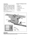
Setting Outfeed Table Height
For accurate work in most jointing operations,
the outfeed table must be exactly level with the
knives/inserts at their highest point of revolution.
The outfeed table on the Model 1285 has been
pre-set at the factory to the proper height in
relation to the cutterhead. However, the level of
the outfeed table should be checked in case of
slight misadjustment during shipping. Outfeed
table height should also be inspected after re-
setting or replacing knives/inserts.
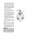
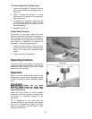
1. The outfeed table has a stop screw (A,
Figure 12) which, when contacting the edge
of the table as shown, will ensure the
outfeed table is at the proper height. Loosen
the handwheel (C, Figure 12) and raise the
outfeed table adjustment arm (D, Figure 12)
until this stop screw (A, Figure 12) contacts
the edge of the table as shown.
Figure 9
Figure 10
Figure 11
Figure 12