14
Setting Infeed Table Height (Depth of
Cut)
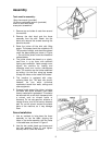
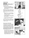
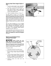
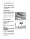
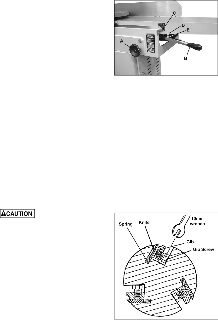
1. To set the cutting depth, loosen handwheel
(A, Figure 17) by turning counterclockwise.
2. Move table adjustment arm (B, Figure 17)
up or down to raise or lower infeed table.
The pointer (C, Figure 17) shows the depth
of cut on the adjoining scale.
3. Tighten handwheel securely (A, Figure 17).
The stop screw (D, Figure 17) on the infeed
table should be set so that when it contacts the
table, the infeed table will be exactly level with
the knives (with the scale pointer at zero). The
setting of this stop screw has been made at the
factory, but should be checked by the operator
before using the jointer. It should also be
checked occasionally as the machine receives
use.
Use the same procedure as for the outfeed
table, placing the straightedge across outfeed
table, cutterhead and infeed table. Loosen the
hex nut (E, Figure 17) and adjust the stop screw
(D, Figure 17) as necessary. When finished,
retighten hex nut (E, Figure 17).
If the infeed table is level with the knives but the
scale pointer (C, Figure 17) appears to be off,
loosen the scale pointer with a screwdriver and
adjust it as needed until it reads zero. Retighten
the screw.
Replacing and Setting Knives
(Straight Cutterhead)
Jointer knives are very
sharp. Use care and proceed slowly when
working with or around the cutterhead.
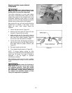
After a period of use, dull knives should be
reground or replaced. Remove the pulley cover
at the rear of the machine – this will allow you to
rotate the cutterhead by using the belts.
To remove a knife:
1. Disconnect machine from power source.
2. Back the fence away from the cutterhead as
far as it will go. Lower infeed and outfeed
tables.
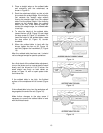
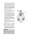
3. Turn the six gib screws (Figure 18) into the
gib with a 10mm wrench. As the pressure of
the gib is released, the two springs in the
cutterhead slot will cause the knife to rise.
4. Carefully remove the knife from the
cutterhead.
Figure 17
Figure 18


