


11
an equipment-grounding conductor and a
grounding plug. The plug must be plugged into a
matching outlet that is properly installed and
grounded in accordance with all local codes and
ordinances. Do not modify the plug provided - if it
will not fit the outlet, have the proper outlet installed
by a qualified electrician.
Improper connection of the equipment-grounding
conductor can result in a risk of electric shock. The
conductor with insulation having an outer surface
that is green with or without yellow stripes is the
equipment-grounding conductor. If repair or
replacement of the electric cord or plug is
necessary, do not connect the equipment-
grounding conductor to a live terminal.
Check with a qualified electrician or service
personnel if the grounding instructions are not
completely understood, or if in doubt as to whether
the tool is properly grounded. Use only 3-wire
extension cords that have 3-prong grounding plugs
and 3 pole receptacles that accept the tool's plug.
Repair or replace damaged or worn cord
immediately.
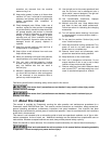
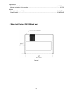
2. Grounded, cord-connected tools intended for
use on a supply circuit having a nominal rating
between 150 – 250 volts, inclusive:
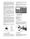
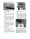
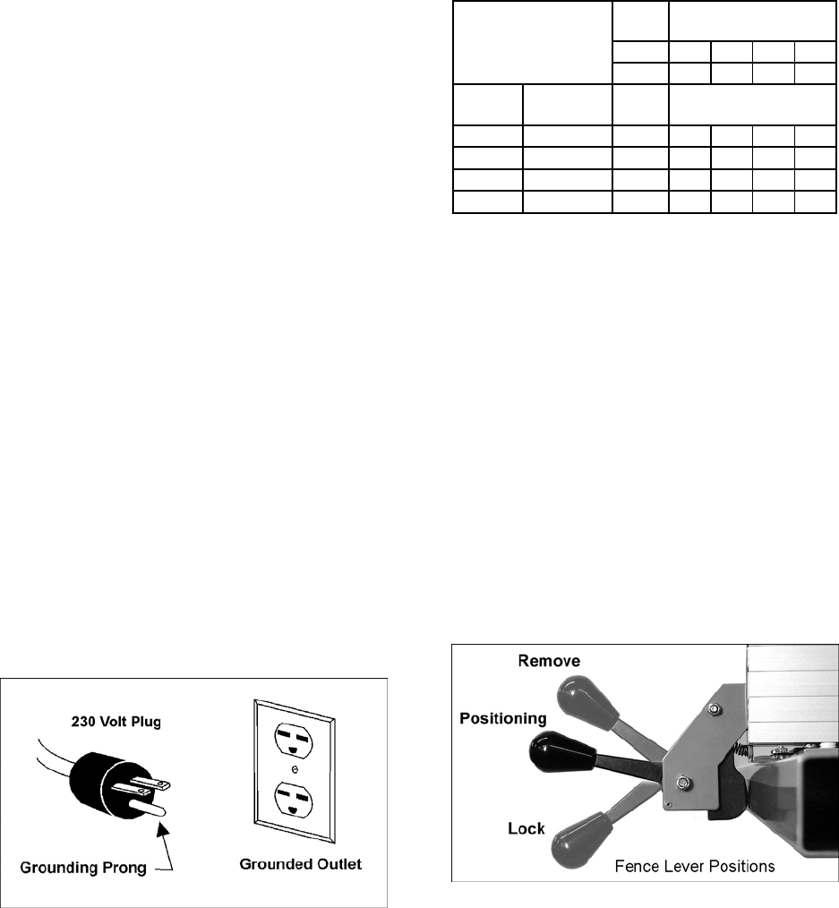
This tool is intended for use on a circuit that has an
outlet that looks like the one illustrated in Figure 4.
The tool has a grounding plug that looks like the
plug illustrated in Figure 4. Make sure the tool is
connected to an outlet having the same
configuration as the plug. No adapter is available
or should be used with this tool. If the tool must be
reconnected for use on a different type of electric
circuit, the reconnection should be made by
qualified service personnel; and after reconnection,
the tool should comply with all local codes and
ordinances.
Make sure the voltage of your power supply
matches the specifications on the motor plate of
the Band Saw.
Figure 4
7.7 Extension Cords
The use of extension cords is discouraged; try to
position machines within reach of power source. If
an extension cord becomes necessary, make sure
the cord rating is suitable for the amperage listed
on the machine’s motor plate. An undersized cord
will cause a drop in line voltage resulting in loss of
power and overheating.
Use Table 1 as a general guide in choosing the
correct size cord. The smaller the gauge number,
the heavier the cord. If in doubt, use the next
heavier gauge.
Recommended Gauges (AWG) of Extension Cords
Ampere rating
Volts Total length of cord
in feet
120 25 50 100 150
240 50 100 200 300
More
than
Not more
than
Minimum gauge cord
0 6
18 16 16 14
6 10
18 16 14 12
10 12
16 16 14 12
12 16
14 12 NR NR
NR: Not Recommended.
Table 1
8.0 Adjustments
Tools required for adjustments:
Machinist square
Cross point (Phillips) screwdriver
Hex keys, 4mm/5mm/6mm
13mm wrench
Straight edge and gauge
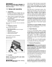
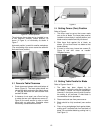
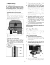
8.1 Fence assembly
Refer to Figure 5.
Place fence body onto guide tube (as shown in
Figure 9). Raise fence lever all the way up to install
or remove fence from guide rail. Midway lever
position allows fence to slide along guide rail.
Lowest lever position locks fence in place.
Figure 5
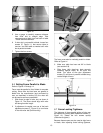
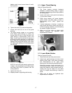
8.2 Fence plate
Refer to Figures 6 and 7.
Loosen lock bar (A) using knobs (B). Pull out on
lock bar until it protrudes enough on which to slide
the aluminum fence plate from one end, as shown
in Figure 6. Retighten knobs.