


14
you should inspect fence-to-blade relationship, as
explained in section 8.6.
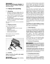
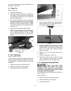
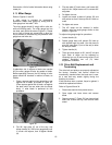
8.8 Table Tilt
Refer to Figure 15.
1. Loosen lock handle (A).
2. For right tilt (as viewed from front or operator’s
side of saw), push on table while rotating knob
(B) clockwise to tilt table up to 45°. Use knob
(B) for fine adjustment.
3. For left tilt (as viewed from front or operator’s
side of saw), loosen lock lever (A) and rotate
knob (B) clockwise a turn or two to release
pressure on the 90° stop bolt (shown in Figure
16). Remove stop bolt, then rotate knob to tilt
table up to 15°.
4. Tighten lock handle (A) to secure setting.
NOTE: The lock handle (A) can be pivoted to
more convenient positions. Simply lift straight
out on handle and rotate it on the pin, then
release handle making sure it seats itself on
the pin.
Figure 15
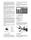
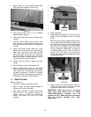
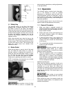
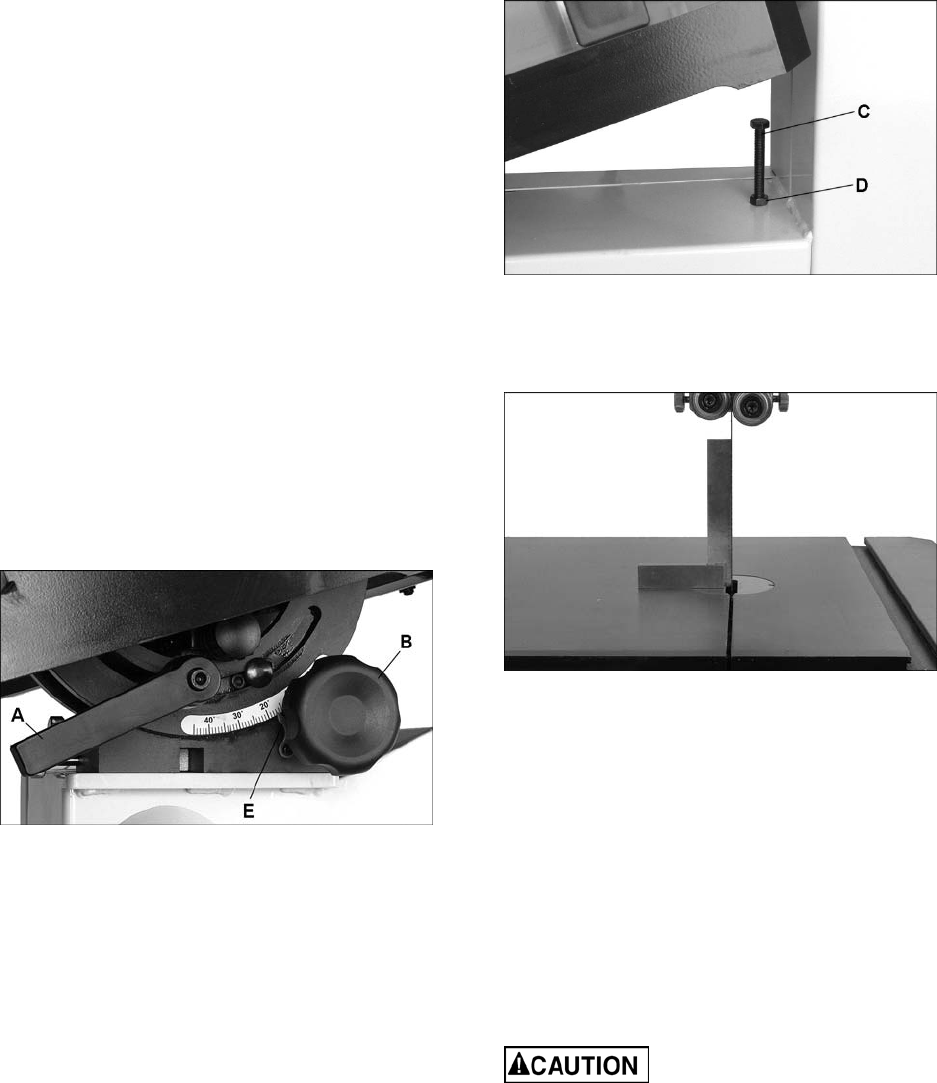
8.9 90° Table Stop
Refer to Figures 16 and 17.
The 90° positive stop ensures that table will always
be perpendicular to blade after table is returned to
horizontal position. Check and adjust this 90° stop
as follows:
1. Disconnect machine from power source.
2. Make sure blade is under full tension.
3. Tilt table until it rests on stop bolt (C).
Figure 16
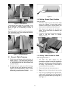
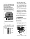
4. Place a square on table and against blade to
check that table is 90° to blade. See Figure 17.
Do not push square into blade.
Figure 17
5. If table and blade are not square, use a 13mm
wrench to loosen lock nut (D, Figure 16) then
rotate stop bolt. Turn stop bolt as needed until
there is no longer light showing between
square and blade.
6. Tighten lock nut (D) to secure table stop in
position.
7. Tighten lock handle (A, Figure 15).
8. Check that scale pointer (E, Figure 15) is at
zero. If necessary, loosen screw on pointer
and shift pointer to zero. Re-tighten screw.
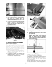
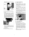
8.10 Installing/Changing Blades
Always wear gloves when
handling blades. New blades are usually
packaged in coiled position; to prevent injury
uncoil them slowly and carefully, while wearing
work gloves and safety glasses.
The PM1800 band saw is designed for blades from
1/8” to 1” wide.
Refer to Figure 18.
1. Disconnect machine from power source.
2. Remove table insert (F, Figure 18).
3. Pull out table pin (G).