


18
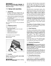
Figure 27
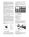
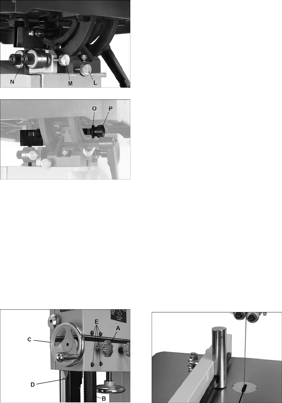
Figure 28
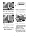
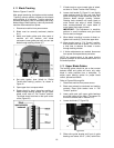
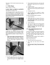
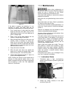
8.16 Guide Post
Refer to Figure 29.
1. Disconnect band saw from power source.
2. Loosen lock knob (A) and raise or lower guide
post (B) using handwheel (C).
3. Position blade guide assembly so that bottom
of guide bearings are about 1/8” above
material to be cut. Or, simply lower guide post
until scale pointer (D) indicates the height of
your workpiece. This provides minimal
clearance between workpiece and bottom of
guide bearings, which will minimize blade
deflection as well as enhance operator safety.
4. Tighten lock knob (A).
Figure 29
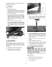
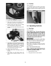
8.17 Guide Post Parallelism
The guide post should be parallel to blade
throughout vertical travel of the guide post; thus the
guide bearings will maintain their relationship to
blade at any height from the table and won’t
require re-setting each time guide post is moved.
This setting has been accurately made by the
manufacturer and should not require immediate
attention, but may be checked in future as follows:
1. Disconnect band saw from power source.
2. Move blade tension lever to “Full Tension”
position.
3. The guide bearings in low position should
already be set in relation to blade (see section
8.13). Also, the table must be square with
blade (see section 8.5)
4. Loosen lock knob (A, Figure 28) and raise
guide post to a high position.
5. Confirm that guide post travels straight up and
down, and guide bearings maintain their
relationship to blade.
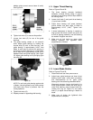
6. If guide post does not go straight up and down
(blade begins deflecting when guide post is
raised), slightly loosen the four screws (E,
Figure 29) and adjust guide post assembly as
needed.
7. When finished adjusting, securely tighten the
four screws (E).
8. Verify the setting by raising and lowering guide
post.
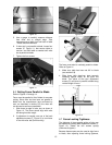
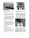
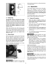
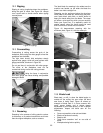
8.18 Resaw Pin
Refer to Figure 30.
The resaw pin provides a single contact point while
ripping a workpiece into thinner boards.
Remove aluminum plate and mount resaw pin to
slot in fence body, securing it with knob, as shown.
The resaw pin is usually positioned so that its
center is approximately even with the front edge of
the blade.
Figure 30