19
See section 10.4 for further information about using
resaw pin.
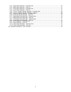
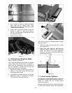
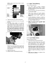
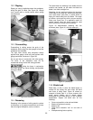
8.19 Miter Gauge
Refer to Figures 31 and 32.
A miter gauge is provided for crosscutting
operations. Install miter gauge by sliding end of
miter gauge bar into table T-slot.
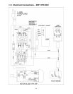
The miter gauge should fit snugly within miter slot
while still sliding easily. The miter gauge bar has
two slots, each with a set screw (Figure 31). Rotate
one or both of these set screws with a 4mm hex
key as needed, to eliminate any play between miter
gauge bar and miter slot.
Figure 31
If table/miter slot is square to blade (see section
8.5) the miter gauge will also be square to blade.
Before operating, however, the 90° setting of miter
gauge should be checked in relation to blade, as
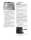
follows.
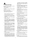
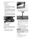
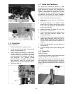
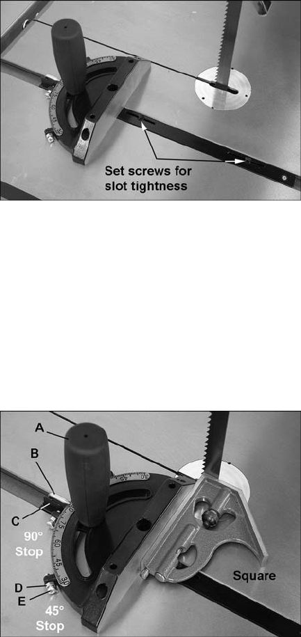
1. Place a square against miter gauge face, and
against flat of blade, as shown in Figure 32.
(Place square against flat of blade, not against
the teeth which are set wider than the blade
body). A wide blade is preferred for this
procedure.
Figure 32
2. Flip 90° stop plate (C) out of the way, and
loosen handle (A). Shift miter gauge body until
it is flush with square, then re-tighten handle
(A).
3. Flip stop plate (C) back down, and loosen 90°
stop hex nut. Adjust screw until it contacts 90°
stop plate.
4. Re-tighten hex nut.
5. Loosen set screw at base of pointer (B) and
shift pointer so that it lines up with 90° mark on
scale.
6. Re-tighten set screw.
7. The 45° stops can be checked in similar
fashion, using an angle gauge similar to that
shown in Figure 32.
To adjust miter gauge angle for operations:
1. Loosen handle (A).
2. Rotate gauge body until pointer (B) lines up
with desired angle on scale. You may have to
pivot 90° stop plate (C) out of the way to allow
the body to rotate.
3. Tighten handle (A).
4. There are three stops: at 90°, and 45° left and
right. Each of these can be adjusted by
loosening hex nut (D) and turning screw (E) as
needed. Re-tighten hex nut (D) when
adjustment is finished.
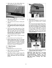
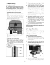
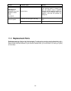
8.20 Drive Belt Replacement and
Tensioning
The drive belt and pulleys are properly adjusted at
the factory. However, belt tension should be
occasionally checked when the band saw is new,
as a new belt may stretch slightly during the
breaking-in process.
If belt becomes worn, cracked, frayed or glazed, it
should be replaced as follows:
Refer to Figures 33 and 34.
1. Disconnect machine from power source.
2. Open upper and lower doors and remove
blade.
3. Remove screw (F, Figure 33) from lower wheel
shaft with a 6mm hex key, and remove lower
wheel.