


17
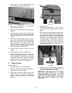
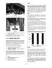
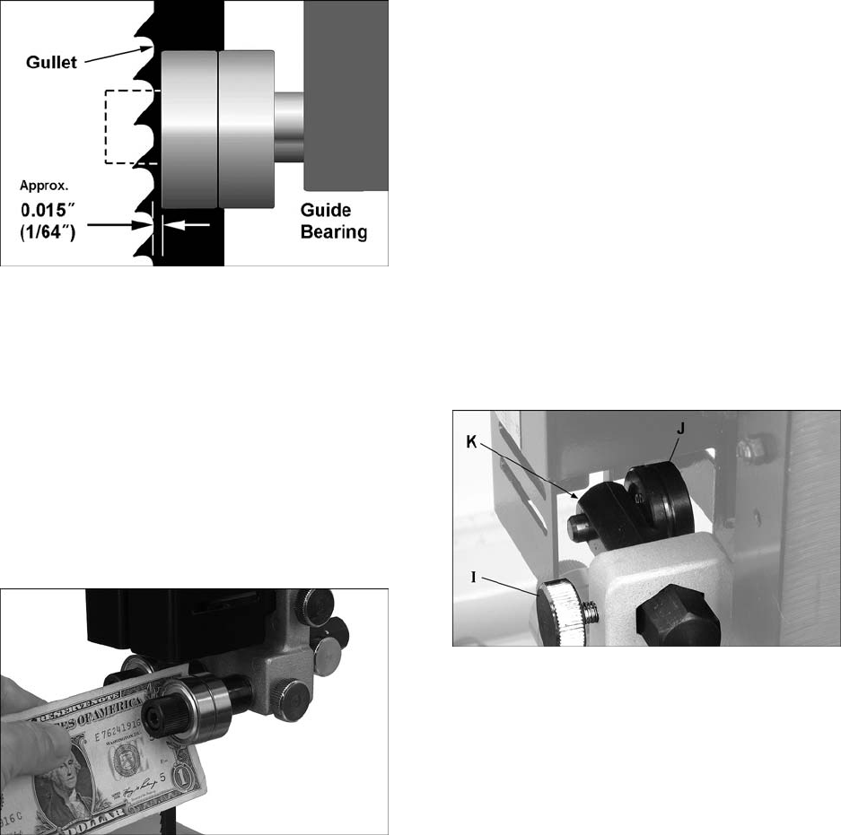
blade’s gullet (curved area at base of tooth).
See Figure 24.
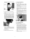
Figure 24
6. Tighten lock knob (F) to secure this position.
7. Loosen lock knob (G) for one of the guide
bearings.
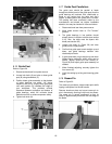
8. The guide bearing rotates on an eccentric
shaft. Adjust guide bearing by rotating the
knurled knob (H) with a 5mm hex key, until
guide bearing is approximately 0.004” from
blade. A quick way to achieve this spacing is
by placing a single thickness of a crisp dollar
bill (a dollar bill is approximately 0.004” thick)
between blade and guide bearing. See Figure
25. Adjust guide bearing until it just lightly grips
the dollar bill.
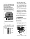
Figure 25
NOTE: Do not force guide bearing against side
of blade. It should generally only make contact
with blade when there is pressure from the
cutting operation.
9. Tighten lock knob (G).
10. Repeat process for opposite guide bearing.
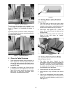
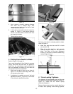
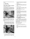
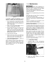
8.14 Upper Thrust Bearing
Refer to Figures 23 and 26:
1. The thrust bearing prevents backward
deflection of blade during cutting. A groove
provided in the bearing surface helps stabilize
the moving blade.
2. Loosen lock knob (I) and push thrust bearing
(J) up to back of blade.
3. Adjust thrust bearing until space between
groove bottom and back edge of blade is
approximately 0.015” (1/64”). Tighten lock
knob (I).
4. If lateral adjustment of bearing is needed to
align groove with blade, loosen set screw (K)
at front of bearing assembly, and shift bearing
as needed. Retighten set screw.
5. Make sure all lock knobs on upper guide
bearing assembly are tightened when
adjustments are finished.
Figure 26
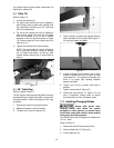
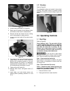
8.15 Lower Blade Guides
Refer to Figures 27 and 28.
1. Disconnect band saw from power source.
2. Adjust lower guide bearings and lower thrust
bearing below table, using same procedure
and measurements as for upper guide
bearings and thrust bearing described above.
Movement summary: Loosen lock knob (L) to
move guide bracket. Loosen lock knob (M) to
rotate side bearing, using knurled knob (N).
Loosen lock ring (O, Figure 27) and rotate
knob (P) to adjust thrust bearing in relation to
blade.
3. Make sure all knobs are tightened after
adjustments are complete.