


16
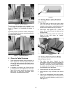
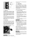
8.12 Blade Tracking
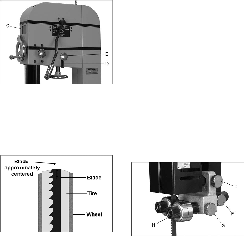
Refer to Figures 21 and 22.
After proper tensioning, the blade must be tracked.
“Tracking” refers to position of blade on the wheels
while machine is in operation. Tracking should be
checked periodically, and is mandatory after every
blade change. Blade tracking is done by hand with
machine disconnected from power.
1. Disconnect machine from power source.
2. Blade must be correctly tensioned (section
8.11).
3. Make sure blade guides and other parts of
machine will not interfere with blade
movement. Lower guide post until you can see
blade through tracking window (C).
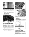
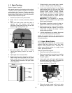
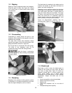
Figure 21
4. Set quick tension lever initially to “Partial
Tension-Idle/Tracking” position, as shown in
Figure 21.
5. Open upper door to expose wheel.
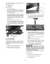
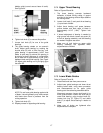
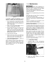
6. Rotate wheel by hand, observing position of
blade through tracking window. As you rotate
wheel, move lever to “Full Tension” position.
The blade should continue to ride upon center
of tire (Figure 22).
Figure 22
7. If blade tends to move toward edge of wheel,
set lever to “Partial Tension-Idle/Tracking.”
8. Loosen lock handle (D, Figure 21) and slightly
rotate tracking knob (E) with your right hand
while continuing to rotate wheel with your left.
Observe blade through tracking window.
Rotating knob clockwise will cause blade to
move toward rear edge of wheel. Rotating
knob counterclockwise will cause blade to
move toward front edge of wheel.
IMPORTANT: This adjustment is sensitive;
perform in small increments and give blade
time to react to changes.
9. When blade is tracking in center of wheel, re-
tighten lock handle (D), and close upper door.
10. Move tension lever to “Full Tension” position,
and connect band saw to power. Turn it on for
a brief time to observe the blade in action
through tracking window.
11. If further adjustments are needed, disconnect
from power and repeat above procedure.
NOTE: An interlock switch in the upper housing
prevents operation of saw unless tension lever is in
full tension position.
8.13 Upper Blade Guides
The bearing guides should be set so that contact
between blade and guides will occur only when
blade is under pressure from a workpiece. To
adjust upper bearing guides for proper blade
control, proceed as follows.
Refer to Figures 23 through 24.
1. Disconnect machine from power source.
2. Blade must already be tensioned and tracking
correctly. Place quick tension lever in “Full
Tension” position.
3. Lower guide post until upper guide bearings
are a few inches off the table. (The reason for
this will be evident later in section 8.17)
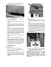
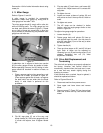
4. Loosen lock knob (F, Figure 23).
Figure 23
5. Slide entire guide bracket until front of guide
bearings are about 0.015” (1/64”) behind the