


12
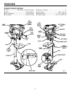
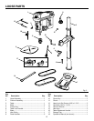
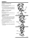
LOOSE PARTS
�1 Head Assembly..................................................... 1
�2 Column Assembly................................................. 1
3� Table...................................................................... 1
�4 Belts...................................................................... 2
�5 Switch Key............................................................ 1
�6 Table Lock Handle ................................................ 1
�7 Base...................................................................... 1
�8 Idler Pulley ............................................................ 1
�9 Feed Handles........................................................ 3
��10 Chuck Key ............................................................ 1
��11 Chuck.................................................................... 1
��12 Head Lock Set Screws, M10 x 1.5-12.................. 2
��13 Hex Bolts, M10 x 1.5-40....................................... 4
��14 Hex Box Wrench................................................... 1
��15 Hex Keys............................................................... 2
��16 Table Adjustment Handle...................................... 1
��17 Storage Tray.......................................................... 1
��18 Operator’s Manual (not shown)............................. 1
Fig. 3
®
®
1
2
3
4
4
5
7
8
9
10
11
12
13
14
15
17
6
16
Key
No. Description Qty.
Key
No. Description Qty.