


22
WARNING:
Before performing any adjustment, make sure the
drill press is unplugged from the power supply
and the switch is in the OFF position. Failure to
heed this warning could result in serious personal
injury.
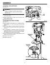
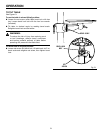
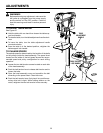
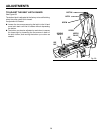
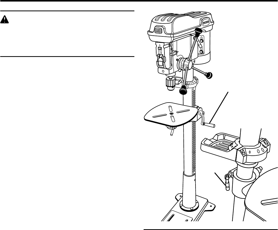
TO ADJUST TABLE HEIGHT
See Figure 22.
n Hold the table with one hand then loosen the table sup-
port lock handle.
n To raise the table, turn the table adjustment handle clock-
wise.
n To lower the table, turn the table adjustment handle
counterclockwise.
n Once the table is in the desired position, retighten the
table support lock handle.
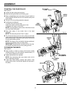
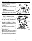
TO CHANGE SPEEDS
The spindle speed is determined by the location of the belts
on the pulleys inside the head assembly. The speed chart
located on the inside of the belt guard shows the recom-
mended speed and pulley configuration for each drilling
operation:
n Loosen the two belt tension screws located on each side
of the head assembly.
n Push the belt tension lever to release belt tension and to
loosen the belts.
n Open the head assembly cover and reposition the belt
according to the speed chart. Close the cover.
n Push the belt tension lever firmly back into position as-
suring drive belt is tight. While holding tension on the
motor, retighten the two belt tension knobs securely.
ADJUSTMENTS
Fig. 22
®
®
TABLE
ADJUSTMENT
HANDLE
TABLE SUPPORT
LOCK HANDLE