


14
ASSEMBLY
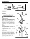
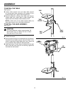
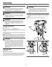
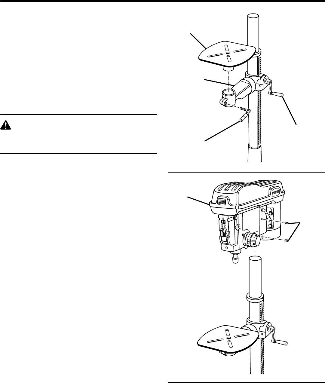
TO INSTALL THE TABLE
See Figure 6.
n Loosen table support lock and raise table support
by turning table crank clockwise until support is at a
working height level. Tighten table support lock.
n Remove protective covering from table and discard.
Loosen table lock, place table in table support and
tighten table lock (located under table) by hand.
NOTE: If table won’t fit into table support easily, pry
open table support with a flat blade screwdriver.
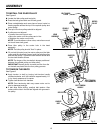
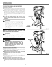
TO INSTALL THE HEAD ASSEMBLY
See Figure 7.
CAUTION:
The head assembly weighs approximately 80
pounds (36.4 kg). To reduce the risk of back
injury get help to lift the head.
n Locate set screws.
n Remove protective bag from head assembly and discard.
Carefully lift head above column tube and slide it onto
column making sure head slides down over column as
far as possible. Align head with table and base.
n Install a set screw in each hole as indicated on the right
side of the head, and using a 5 mm hex key, tighten the
two head lock set screws.
Fig. 6
®
Fig. 7
TABLE
LOCK
TABLE
CRANK
TABLE
TABLE
SUPPORT
®
®
HEAD
ASSEMBLY
SET
SCREWS