


13
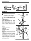
TOOLS NEEDED
ADJUSTABLE
WRENCH
PHILLIPS
SCREWDRIVER
ASSEMBLY
WARNING:
Do not connect to power supply until assembly
is complete. Failure to comply could result in
accidental starting and possible serious injury.
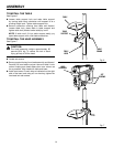
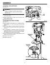
TO ATTACH THE COLUMN ASSEMBLY TO THE
BASE
See Figure 4.
n Locate four hex head bolts.
n Position base on flat surface. Remove protective
covering and discard.
n Remove protective sleeve from column tube and
discard. Place column assembly on base, and align
holes in column support with holes in base.
n Install a hex head bolt in each hole through column
support and base and tighten with adjustable wrench.
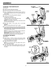
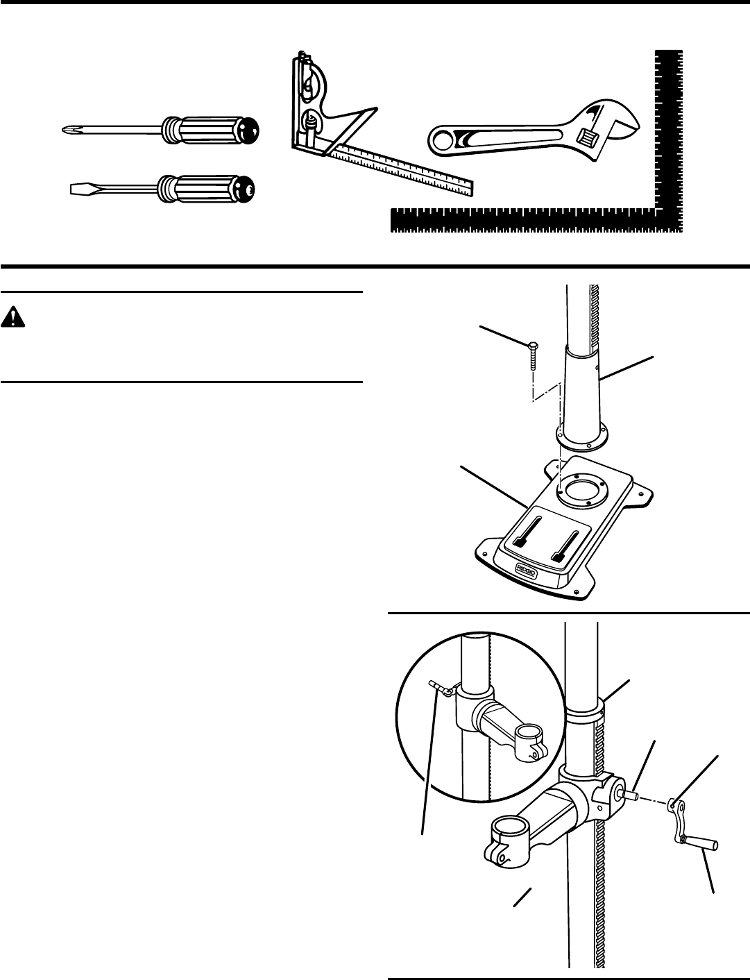
TO ATTACH THE TABLE CRANK AND TABLE
LOCK
See Figure 5.
n Locate table crank and table lock.
n Install table lock from left side into table support and
tighten by hand.
n Install table crank assembly.
n Tighten set screw with a 3 mm hex key. Do not
overtighten.
NOTE: Set screw should be tightened against the flat
section of the shaft.
NOTE: To minimize crank backlash, tighten table lock,
rotate elevation worm shaft clockwise, then assemble
crank tight against table support and tighten set screw.
n Check column collar for proper adjustment. Collar
should not be angled on the column and it should be
positioned so rack will slide freely in collar when table
is rotated 360° around column tube. If readjusted, only
tighten set screw enough to keep collar in place.
NOTE: To reduce the risk of column or collar damage,
do not overtighten set screw.
Fig. 4
Fig. 5
The following tools (not included) are needed:
FRAMING
SQUARE
COMBINATION
SQUARE
FLAT BLADE
SCREWDRIVER
®
HEX BOLT
COLUMN
ASSEMBLY
BASE
®
TABLE CRANK
SET
SCREW
ELEVATION
WORM
SHAFT
TABLE
SUPPORT
LOCK
COLLAR
TABLE
LOCK