


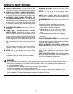

12
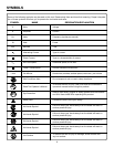
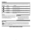
13
FEATURES
BLADE GUARD - Always keep the guard down over the
blade for through-sawing cuts.
BLADE HEIGHT LOCK KNOB - This knob, in the center of the
height adjusting handwheel, locks the handwheel into place
and must be unlocked before turning the handwheel.
BEVEL LOCK LEVER - This lever, placed just under the
worktable surface on the front of the cabinet, locks the angle
setting of the blade. Be sure the lever is unlocked before
tilting the blade. If it is not unlocked, it may jam and bend
the locking bolt.
HEIGHT ADJUSTING HANDWHEEL - Use this handwheel
to lower and raise the blade for adjustments or replacement.
It is located on the front of the cabinet.
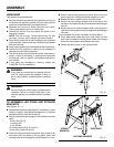
HERC-U-LIFT MOBILE BASE
TM
- This saw comes with a
mobile base that allows for easy mobility.
IND-I-CUT™ ALIGNMENT DISC - A plastic insert on which
marks may be made to indicate the location of the cut on
the workpiece.
LOCKING LEVER - The lever on the front of the rip fence
releases the rip fence or locks it in place.
MITER GAUGE - This miter gauge aligns the wood for a
crosscut. The easy-to-read indicator shows the exact angle
for a miter cut, with positive stops at 90° and 45°.
MITER GAUGE GROOVES - The miter gauge rides in these
grooves on either side of the blade.
MOTOR - The powerful induction motor, with capacitor start
and poly V-belt drive, is housed in a sturdy steel base.
RAILS - Front and rear rails provide support for the rip fence
and extension tables.
RIP FENCE - A sturdy metal fence guides the workpiece and
is secured with the locking lever. Grooves run along the top
and sides of the rip fence for use with clamps and jigs.
SCALE - Found on the front rail, the easy-to-read scale
provides precise measurements in rip cuts.
SEPARATOR OR SPLITTER - A metal piece, slightly thin-
ner than the saw blade which helps keep the kerf open and
prevent kickback.
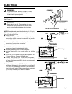
SWITCH ASSEMBLY - Your table saw has an easy access
power switch located below the front rail. The yellow switch
key must be removed from the blister pack and inserted
into the switch before the saw can be operated. To lock the
switch in the OFF position, remove the switch key from the
switch. Place the key in a location that is inaccessible to
children and others not qualified to use the tool.
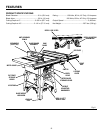
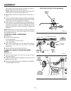
KNOW YOUR TABLE SAW
See Figure 6.
Before attempting to use this product, familiarize yourself
with all operating features and safety rules.
OVERVIEW
The upper portion of the blade projects up through the table,
surrounded by an insert called the throat plate. The height
of the blade is set with a height adjusting handwheel on the
front of the cabinet. Detailed instructions are provided in the
Operation section of this manual for the basic cuts: rip cuts,
cross cuts, miter cuts, bevel cuts, and compound cuts.
For cuts with the blade straight up and cutting across the
grain (cross cuts or miter cuts), use the miter gauge to set
the angle and push the wood into the blade. To cut with the
blade straight up, along the grain of the wood (rip cuts), use
the rip fence to guide the wood. Push smaller pieces with
a push block or push stick.
To tilt the blade for a bevel cut, use the bevel adjusting hand-
wheel on the side of the cabinet. A bevel scale on the front
of the cabinet shows the blade angle. Inside the cabinet,
adjustable positive stops control the degree of tilt which
can be adjusted with the screws in the top of the saw table.
Use the miter gauge for a bevel cross cut (compound cut)
and the rip fence for a bevel rip cut.
Your saw is designed to perform as a versatile, accurate,
precision cutting tool that is easy to operate. It is equipped
with the following features for convenience, ease of use, and
high-quality performance:
ANTI-KICKBACK PAWLS - Kickback is a hazard in which the
workpiece is thrown back toward the operator. The toothed
pawls are designed to snag the workpiece to prevent or
reduce injury should kickback occur.
BEVEL ADJUSTING HANDWHEEL - Use this handwheel
to set the angle of the blade for bevel cuts. It is located on
the side of the cabinet.
BEVEL SCALE - The easy-to-read scale on the front of the
workstand shows the exact blade angle.
BLADE - For maximum performance, it is recommended
that you use the 40-tooth, 10 in. (254 mm) carbide tipped
combination blade provided with your saw. Additional blade
styles of the same high quality are available for specific op-
erations such as ripping. Your local dealer can provide you
with complete information.
WARNING:
Do not use blades rated less than the speed of
this tool. Failure to heed this warning could result
in personal injury.