


44
45
®
0
5
10
15
20
25
30
35
40
45
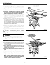
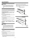
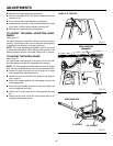
n Reinstall the height adjusting handwheel.
n With the saw blade at 45˚, the bevel indicator should be
pointing to 45˚.
n If not, remove the height adjusting handwheel.
n Loosen the two screws on the scale and adjust the scale
up or down until the bevel indicator points to 45˚.
n Reinstall the height adjusting handwheel.
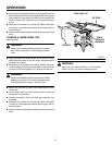
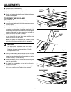
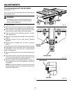
TO ADJUST THE BEVEL ADJUSTING HAND-
WHEEL
See Figure 74.
The bevel adjusting handwheel should turn freely without
binding. The turning friction can be adjusted by tightening
or loosening the screws in the bearing retainer.
NOTE: The bevel adjusting handwheel must be removed
to make this adjustment. When adjusting the screws in the
bearing retainer, hold the nut inside using a 3/8 in. wrench.
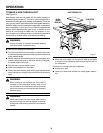
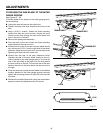
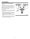
TO ADJUST THE MITER GAUGE
See Figure 75.
You can set the miter gauge at 0˚ and plus or minus 45˚ with
the miter gauge stop pin and adjustable stop screws.
NOTE: The miter gauge provides close accuracy in angled
cuts. For very close tolerances, test cuts are recommended.
n Loosen the lock knob and pull out on stop pin to rotate
miter gauge base past stop screws.
n Loosen the lock nut of the 0˚ stop screw at the stop pin
with a wrench.
n Place a 90˚ square against the miter gauge rod and the
miter gauge base.
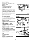
n If the rod is not square, loosen the lock knob, adjust the
rod, and retighten the knob.
n Adjust the 0˚ stop screw until it rests against the stop
pin.
n Adjust the plus and minus 45˚ stop screws using a 45˚
triangle and the steps above.
ADJUSTMENTS
Fig. 74
Fig. 75
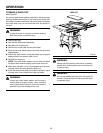
Fig. 76
45
30
15
6
0
6
0
45
1
5
3
0
0
0° LOCK NUT
BLADE AT 45˚ POSITION
BEVEL ADJUSTING
HANDWHEEL
90° LOCK NUT
MITER GAUGE ROD
LOCK KNOB