


16
17
ASSEMBLY
UNPACKING
This product requires assembly.
n Remove the packing materials from around your tool. Do
not discard the packing material until you have carefully
inspected and satisfactorily operated the tool.
n Separate and remove all loose parts from the carton.
Check parts against the list of loose parts.
n Carefully lift the tool from the carton and place it on a
level work surface.
NOTE: This tool is heavy. To avoid back injury, lift with
your legs, not your back, and get help when needed.
n Remove the protective oil that is applied to all unpainted
metal surfaces. Use any ordinary household type grease
and spot remover.
n Apply coat of paste wax to the table and table extensions.
n Inspect the tool carefully to make sure no breakage or
damage occurred during shipping.
n The saw is factory set for accurate cutting. After assem-
bling it, check for accuracy. If shipping has influenced
the settings, refer to specific procedures explained in
this manual.
n If any parts are damaged or missing, please call
1-866-539-1710 for assistance.
WARNING:
If any parts are missing do not operate this tool
until the missing parts are replaced. Failure to
do so could result in possible serious personal
injury.
WARNING:
Do not connect to power supply until assembly is
complete. Failure to comply could result in ac-
cidental starting and possible serious personal
injury.
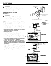
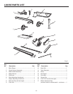
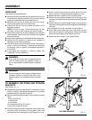
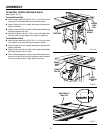
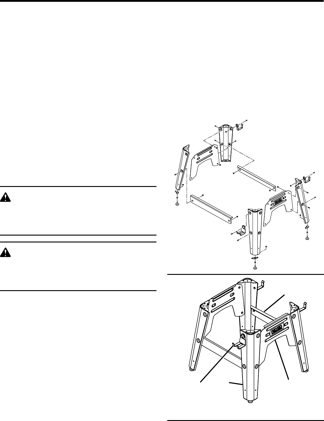
TO ASSEMBLE LEG STAND AND STORAGE
BRACKETS
See Figures 10 - 11.
n Separate the following: side panel (2), front brace (1), back
brace (1), legs (4), miter gauge storage hook (1), rip fence
storage hooks (2), and foot braces (4).
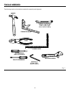
n Remove the following hardware from the blister hardware
pack:
8 hex nuts (3/8-16)
4 leveling feet
4 foot braces
16 carriage bolts (5/16-18 x 5/8 in.)
16 hex nuts, flanged (5/16-18)
n Place front brace inside first leg piece. Align holes on the
front brace with the holes on the leg piece. Insert two
carriage bolts and hand tighten using flanged hex nuts.
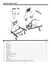
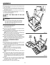
Fig. 10
Fig. 11
LEG STAND ASSEMBLED
LEG
FRONT BRACE
SIDE
BRACE
STORAGE
BRACKET(S)
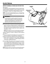
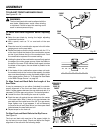
n Attach a second leg piece to the other side of the front
brace using two carriage bolts and flanged hex nuts.
n Repeat the above steps once for the back brace.
n Secure the miter gauge storage hook to the leg on the
left side of the leg stand using a carriage bolt and flanged
hex nut.
n Secure the two rip fence storage hooks to the leg on the
right side of the leg stand using carriage bolts and flanged
hex nuts.
This completes two of the four sides of the leg stand.
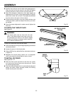
n Place side brace inside leg piece. Align holes on side
brace with the holes on the leg piece. Insert two carriage
bolts and hand tighten using flanged hex nuts.
n Repeat the above step on the opposite side.