


20
21
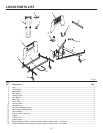
ASSEMBLY
Fig. 16
Fig. 17
Fig. 18
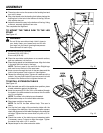
UNLOCK
PEDAL
CENTER U-BOLT WITHIN THE LATCH MECHANISM
®
0
5
10
15
20
25
30
35
40
45
®
0
5
10
15
20
25
30
35
40
45
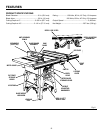
HEIGHT
ADJUSTING
HANDWHEEL
BEVEL
ADJUSTING
HANDWHEEL
LOCK
TUBE
BLADE
HEIGHT
LOCK KNOB
SCREW
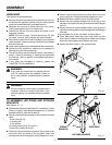
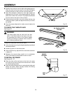
of the tube of the lower section as shown in figure 15.
Secure using the flat washer and lock nut.
NOTE: Tighten the lock nuts until flush with the bottom
of the screw. The screw should freely pivot.
n Repeat above step for the upper section of the Herc-U-
Lift™.
n Check to insure the upper and lower sections are centered.
If required, loosen frame hardware and adjust the frames
side to side to center. Retighten all hardware.
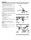
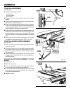
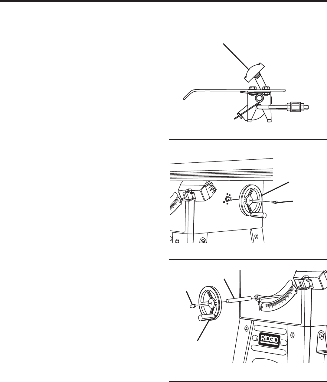
n Press down on the unlock pedal to check alignment of
the U-bolt. The U-bolt should be centered within the latch
mechanism as shown in figure 16. Release the unlock
pedal and adjust the U-bolt as necessary. Retighten all
hardware.
NOTE: With the tool on a level surface, check to make sure
the tool does not move. If tool moves, adjust all four leveling
feet supporting the tool.
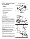
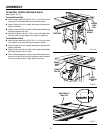
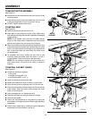
TO INSTALL BEVEL HANDWHEEL
See Figure 17.
n Locate the following parts:
1 bevel handwheel
1 pan head screw (1/4-20 x 5/8 in.)
1 star lock washer
n Push bevel handwheel onto the bevel shaft aligning
flats on the bevel shaft with the flats on the bevel
handwheel.
n Secure using star lock washer and screw.
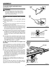
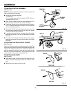
TO INSTALL HEIGHT ADJUSTING HAND-
WHEEL
See Figure 18.
n Remove blade height lock knob by turning the knob
counterclockwise.
n Slide the height adjusting handwheel onto the rod and
against the lock tube.
n Secure the height adjustment handwheel by reinstalling
the blade height lock knob.