


26
27
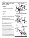
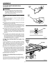
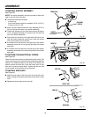
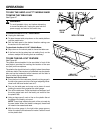
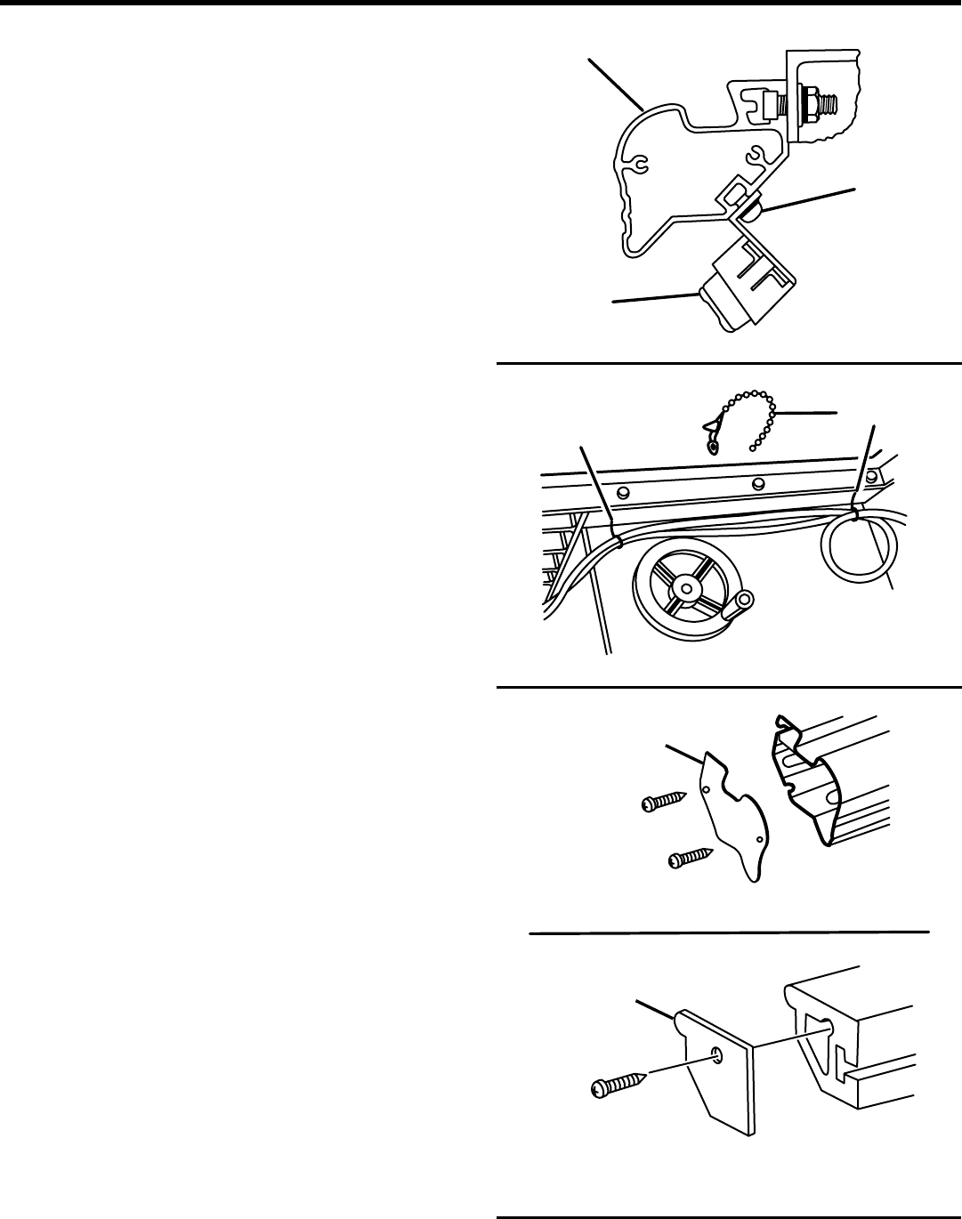
Fig. 38
TO INSTALL SWITCH ASSEMBLY
See Figure 38.
NOTE: The switch assembly may be mounted on either the
right or the left side of the saw.
n Locate the following hardware:
1 switch key
2 pan head screws with lock washers (10-32 x 3/8 in.)
2 square nuts (10 x 32)
n Insert the pan head screws with lock washers (10-32 x
3/8 in.) through the holes in the switch assembly.
n Thread the square nuts on the screws leaving at least a
1/8 in. clearance between the inside of the nut and the
top of the switch assembly.
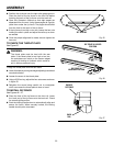
n From either the left end or the right end of the front rail,
with the switch assembly facing front, slide the square
nuts into the lower slot of the rail.
n If mounted from the left end, the right side of the switch
assembly should be in line with the left side of the table
saw base.
n If mounted from the right end, the left side of the switch
assembly should be in line with the right side of the table
saw base.
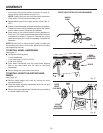
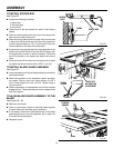
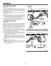
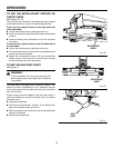
TO SECURE THE ELECTRICAL CORDS
See Figure 39.
Three wire ties come with your table saw (one is extra). The
motor cord and power cord should be routed along side the
cabinet. Two holes provided on the side of the cabinet are
used to secure the wire ties. Loop the motor cord in rear
wire ties to remove excess slack. Lightly tap the wire ties
into the holes of the cabinet using a hammer.
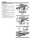
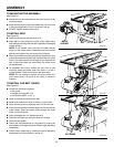
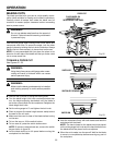
TO INSTALL END CAPS
See Figure 40.
n Align the end caps of the front rail to the end of the rail.
Secure using self-tapping pan head screw (M4) in each
hole.
n Repeat the above step for the rear rail.
Fig. 39
Fig. 40
ASSEMBLY
END CAP
END CAP
PAN HEAD
SCREW
FRONT RAIL
REAR RAIL
WIRE TIE
WIRE TIE
SWITCH
ASSEMBLY
FRONT RAIL