


18
19
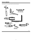
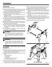
ASSEMBLY
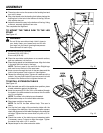
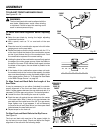
n Thread one hex nut on the screw on the leveling foot and
turn until it stops.
n Slip a foot brace onto the leveling foot before placing the
leveling foot in the hole in the bottom of the leg. Secure
with another hex nut.
n Adjust the feet all the way to the bottom of the leg. Using
a wrench, securely tighten all hex nuts.
This completes the leg stand.
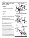
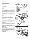
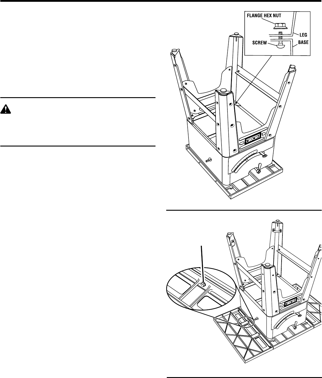
TO MOUNT THE TABLE SAW TO THE LEG
STAND
See Figure 12.
WARNING:
Do not lift the saw without help. Hold it close to
your body. Keep your knees bent and lift with
your legs, not your back. Ignoring these precau-
tions can result in back injury.
n Locate the following hardware:
8 screws (5/16-18 x 5/8 in.)
8 hex nuts (5/16-18)
n Place the saw table upside down on a smooth surface,
such as cardboard, on the floor.
n Place the leg stand on the table saw base. Align the holes
in the table with the holes in the legs.
NOTE: The front panel is the one with the Ridgid logo
and must be on the front of the saw base.
n Insert a screw through the hole in the saw base and the
hole in the leg stand. Add a hex nut. Hand tighten.
n Repeat for remaining holes. Tighten all hardware with a
wrench. You may find it helpful to use one wrench to hold
the head of the bolt and one to tighten the hex nut.
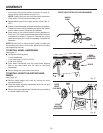
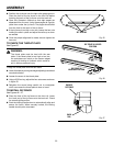
TO INSTALL EXTENSION TABLES
See Figure 13.
n With the table saw still in the upside down position, place
a table extension against the table top.
n Insert four screws (5/16-18 x 3/4 in. with washer) through
the holes in the table extension and screw into the table
top. Do not tighten.
NOTE: The holes in the table top are threaded.
n Repeat above step on the other table extension.
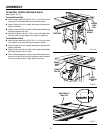
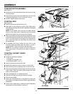
n Stand saw upright on leg stand.
NOTE: Do not lift the saw without help. This saw is
heavy.
n Line up the front edge of the extension table with the
front edge of the table top. Using a combination square,
check the alignment of the table top edge to the extension
rail edge. Tighten the two corner nuts only with a 1/2 in.
wrench.
n Check the center of the table top and extension table.
If necessary, use a C-clamp to align the edges. Tighten
the center nuts with a 1/2 in. wrench.
n Repeat steps for the other extension table.
Fig. 13
®
Fig. 12
®
SCREW
WITH
WASHER