


42
43
®
0
5
10
15
20
25
30
35
40
45
ADJUSTMENTS
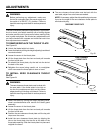
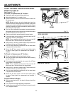
TO SET THE BEVEL INDICATOR AND BEVEL
STOPS AT 0˚ AND 45˚
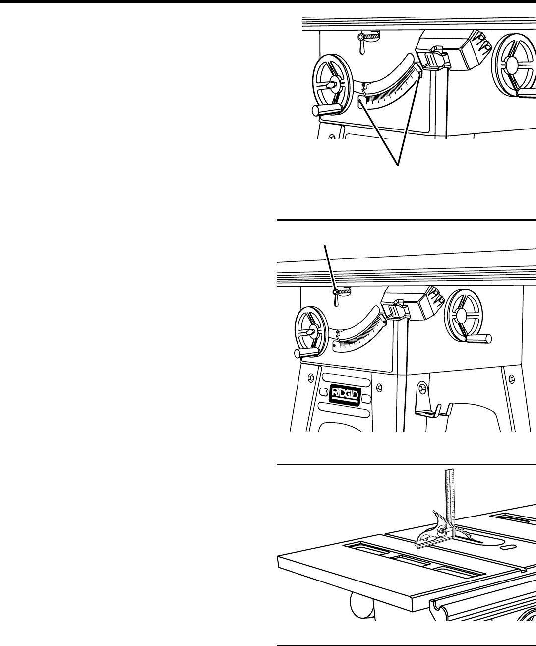
See Figures 70 - 73.
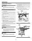
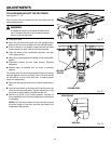
To Check for Squareness, 90˚ Position:
n Unplug the saw and remove the switch key.
n Raise the blade to a 3 in. depth of cut.
n Push the bevel lock lever counterclockwise to loosen the
tilt clamp screw.
NOTE: Bevel lock lever is spring loaded and must be
pushed inward for disengaugement whenever it becomes
necessary to obtain a new grip on the screw head. Always
position the bevel lock lever downward to prevent binding
when tilting the saw blade.
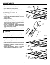
n Turn the bevel adjusting handwheel counterclockwise.
Saw blade should now be square with the saw table and
the bevel indicator should point to 0˚.
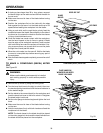
n Place a combination square against the saw blade.
n If the saw blade is not square to the saw table, the 90˚
stop screw needs to be adjusted.
NOTE: From a position at the front of the saw, the 90˚
stop screw is on the left side of the throat plate.
n Using a 3/16 in. hex key, unscrew the 90˚ stop screw until
it is even with the top of the saw table.
n Turn the bevel adjusting handwheel until the saw blade
is square with the saw table.
n Screw the 90˚ stop screw until the saw blade starts
to move. Check again for squareness and readjust if
needed.
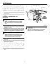
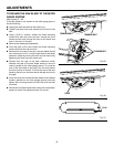
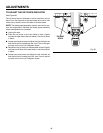
To Check for Squareness, 45˚ Position:
n Tilt the saw blade as far to the left as it will go.
n Place an accurate square against the saw blade checking
for the 45˚ angle.
n If the angle of the saw blade is not correct, the 45˚ stop
screw needs to be adjusted.
NOTE: From a position at the front of the saw, the 45˚
stop screw is on the left side of the throat plate.
n Using a 3/16 in. hex key, unscrew the 45˚ stop screw until
it is even with the top of the saw table.
n Turn the bevel adjusting handwheel until the saw blade
is square with the saw table.
n Screw the 45˚ stop screw until the saw blade starts
to move. Check again for squareness and readjust if
needed.
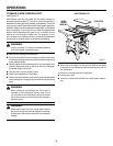
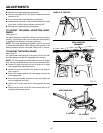
To Set the Bevel Indicator:
n With the saw blade at 90˚, the bevel indicator should be
pointing to 0˚.
n If not, remove the height adjusting handwheel.
n Loosen the screw and position the bevel indicator to point
to 0˚. Retighten screw.
Fig. 71
Fig. 72
Fig. 73
®
®
0
5
10
15
20
25
30
35
40
45
SCREWS
BLADE AT 90˚ POSITION
BEVEL LOCK LEVER