


24
25
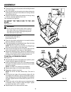
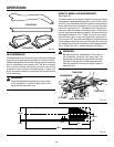
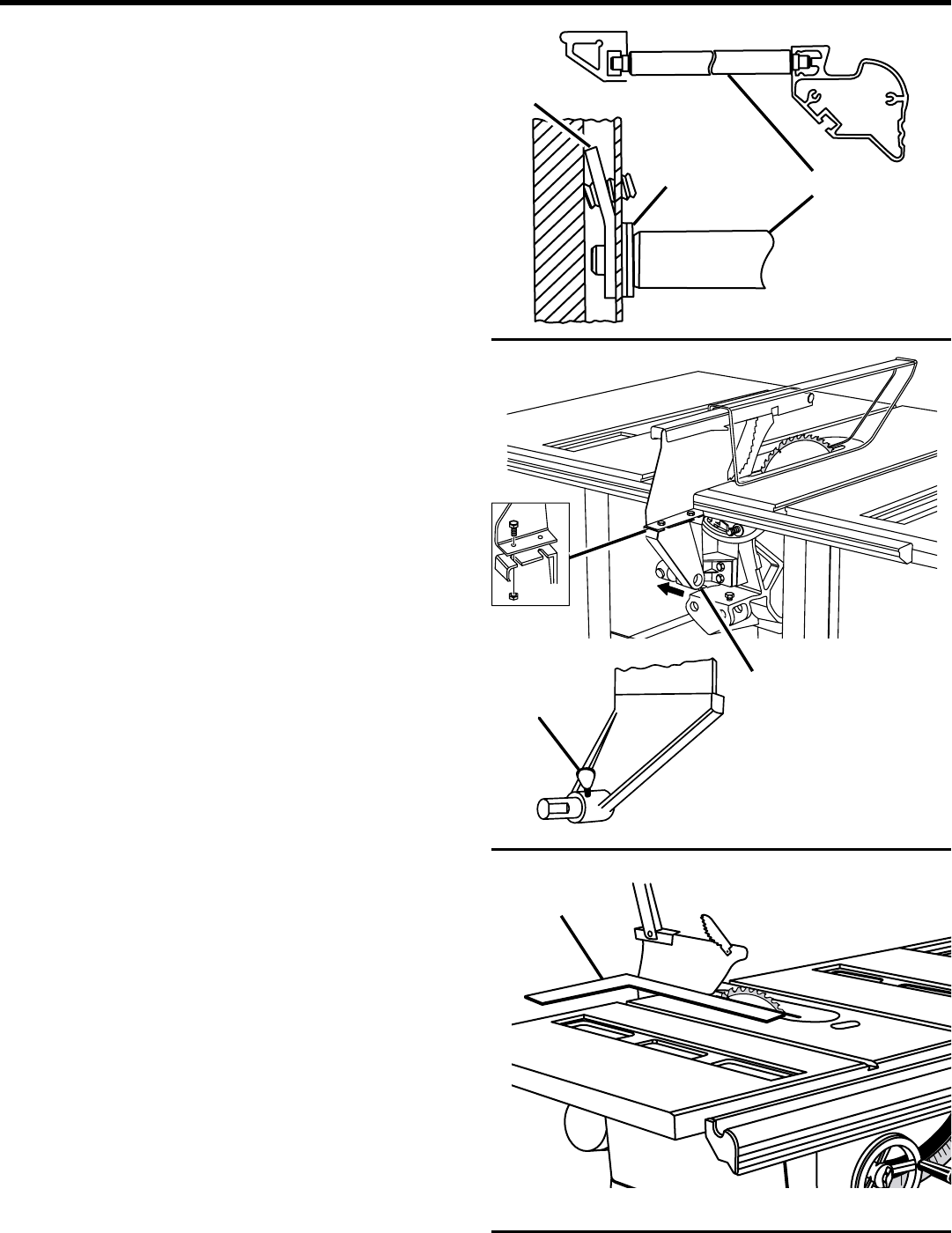
Fig. 28
ASSEMBLY
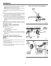
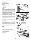
TO INSTALL SPACER BAR
See Figure 28.
n Locate the following hardware:
1 spacer bar
2 locking plates
2 set screws
n Thread one of the set screws into each of the locking
plates.
n Place one locking plate over each end ot the spacer bar
with the bent ends pointing out.
n Slide the locking plate (set screw end first) into the slots
in the end of the front and rear rails. Move the spacer bar
to within approximately 4-1/2 in. from the end of the rear
rail and parallel to the side of the saw table.
n If spacer bar has a gap between the large diameter of the
spacer bar and the inside of the rear rail, fill the gap with
the appropriate number of shims (included). The shims
are to be placed on the spacer bar before the locking
plate.
n Once the correct fit is made, lock the spacer bar in place
by tightening the set screws with a 3/32 in. hex key.
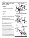
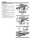
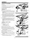
TO INSTALL BLADE GUARD ASSEMBLY
See Figure 29.
n Lower the blade by turning the height adjusting handwheel
counterclockwise.
n Attach the separator to the separator support and align
the edges. Secure using hex head screws (1/4-20 x
5/8 in.) and flanged hex nuts (1/4-20). Tighten using a
10 mm wrench.
n Slide the separator on the separator rod until the notches
engage the pin. Thread thumbscrew into the tapped hole
and hand tighten.
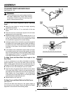
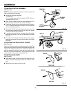
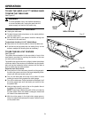
TO ALIGN BLADE GUARD ASSEMBLY TO THE
BLADE
See Figures 29 - 30.
n Raise the saw blade.
n Place a combination square or framing square against
the saw blade and the blade guard assembly.
n If not square, loosen the socket head screw in the blade
guard support and move the separator left or right until
it touches the blade square.
n Retighten screw.
Fig. 29
Fig. 30
®
SHIMS
SPACER BAR
LOCKING
PLATE
THUMB-
SCREW
MOVE LEFT
OR RIGHT FOR
ADJUSTMENT
FRAMING
SQUARE