


46
ADJUSTMENTS
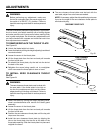
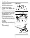
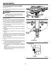
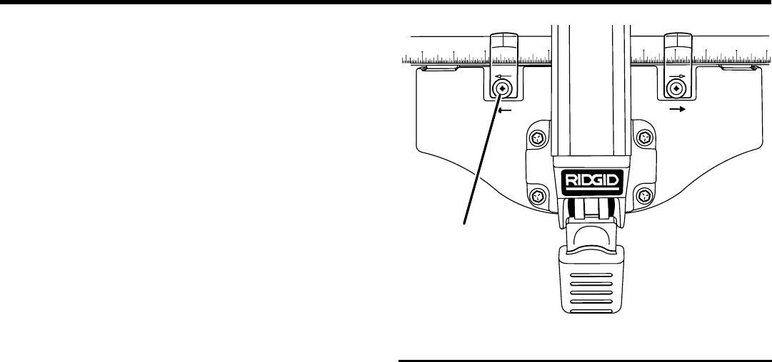
TO ADJUST THE RIP FENCE INDICATOR
See Figure 80.
The rip fence has two indicators: one for use when the rip
fence is on the right side of the saw blade and one for use
when the rip fence is on the left side of the saw blade.
NOTE: The blade guard assembly must be removed to per-
form this adjustment. Reinstall the blade guard assembly
when the adjustment is complete.
n Unplug the saw.
n Place the rip fence on the saw table so that it lightly
touches the right side of the saw blade. Lock the rip fence
in place.
n Loosen pan head screw and adjust the right indicator so
that the red line is located over the "zero" line on the right
rip scale on the front rail. Retighten screw.
n Reposition the rip fence on the saw table so that it lightly
touches the left side of the saw blade. Lock the rip fence
in place.
n Loosen pan head screw and adjust the left indicator so
that the red line is located over the "zero" line on the left
rip scale on the front rail. Retighten screw.
Fig. 80
19
18
25
26
24
23
22
17
16
15
®
PAN HEAD
SCREW