


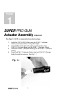
SUPER PRO GUN &
SUPER PRO GUN II
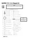
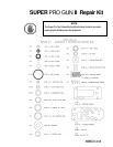
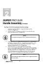
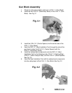
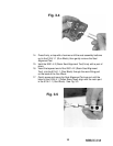
3. Screw the 5105-10-1 (Trigger Nut) into the 5110-7-1 (Gun Handle)
and tighten. Coat the 5110-4-1 (trigger stem) with 6706-3-1 (Pro
Gun Oil) and install from the inside cavity of the 5110-7-1 (Gun
Handle) through the 5105-10-1 (trigger nut).
4. Place the 5105-15-01 (Pivot Plate) into the slot in the
5110-7-1 (Gun Handle Assembly), and push the 7203-4-10
(Slotted Spring Pin) located on the backside of the 5105-16-1
(Trigger) into the hole in the 5110-4-1 (Trigger Stem). Line up the
5105-15-2 (Pivot Plate Bushing) to the lower pivot hole in the Gun
Handle, insert the 7102-10-12 (Slotted Flat Head Screw) and
tighten.
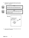
5. Set the 9203-2-1 (Compression Spring) into the spring seat
located in the upper cavity of the 5110-7-1 (Gun Handle).
Set the 5110-3-1 (two position gun detent plate) over the 9203-2-1
(Compression Spring). The elevated shoulder of the 5110-3-1
(two position detent plate) faces up.
6. Place the small pinhole in the 5110-2-1 (Slide Valve) over the pin
through the 5110-4-1 (Trigger Stem), and push down
compressing the spring into the handle cavity.
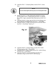
7. Place the 5110-5-1 (Gun Handle Gasket) over the screws,
matching the slot to the slot in the 5110-7-1 (Gun Handle).
8. Lightly lubricate the topside of the 5110-1-1 (Porting Plate) with
6706-3-1 (Pro Gun Oil) and push it over the 5110-2-1 (Slide Valve)
keeping the Slide Valve connected to the 7203-4-9 (Slotted Spring
Pin) in the 5110-4-1 (Trigger Stem).
NOTE
Once in place the spring of the 7304-4-1 (Lip Seal) should be facing out.
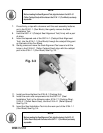
NOTE
When installing the Trigger Assembly the 5105-8-1 (Trigger Lock) must be in
the “down” position. You may find it easier to assemble the gun handle by
placing the flats at the back of the 5110-7-1 (Gun Handle) in a vise. This will
support the rear screws (5105-13-1) from pushing down during assembly.
NOTE
For 2-stage chopper only.
5