


Parameter list
S1A53844 01/2011 55
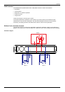
Monitoring and control of I/O from communication
The digital inputs, digital outputs, analog input and output signals of the drives can be controlled by
communication.
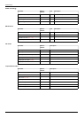
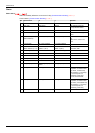
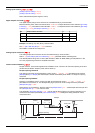
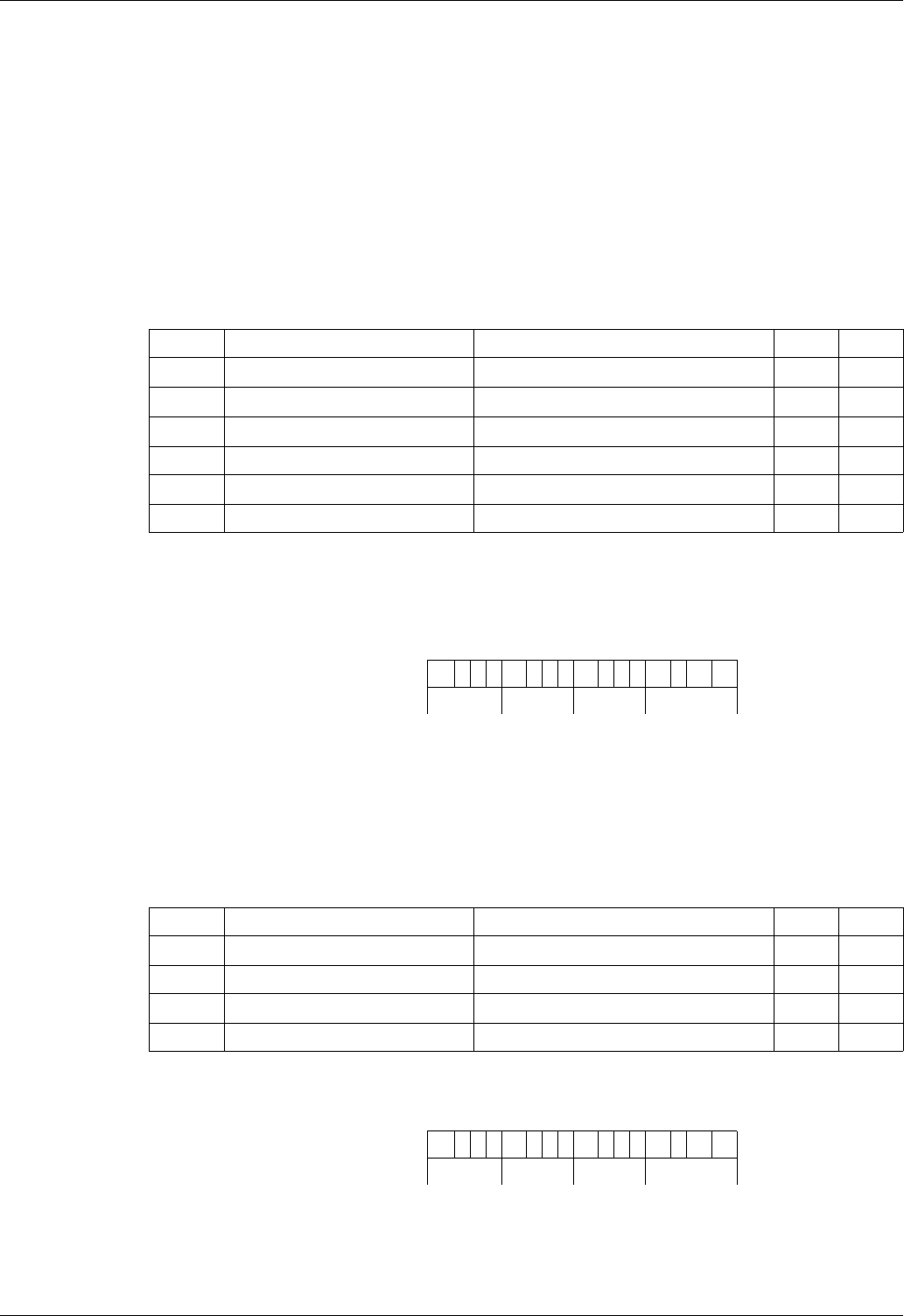
Digital inputs status (Fd06, FE06)
Digital inputs status immediately before the occurrence of a trip: [Status of input terminal block] (FE06)
Current digital inputs status: [Status of input terminal block] (Fd06)
In case "0: No assignment function" is selected in function selection, drive operations will not be affected even
when terminals are turned
on and off. Therefore, the terminals can be used as input terminals for customer's own use.
The input terminal function selection parameter is used to select a function for each input terminal.
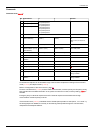
(1): It is valid only when it is selected as contact input by [VIA Input Function] (F109).
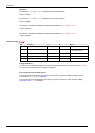
Example: When both F and RES terminals are ON: FE06 = 16#0005
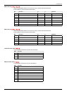
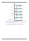
Digital outputs status (Fd07, FE07)
Digital outputs status immediately before the occurrence of a trip: [Status of output terminal block] (FE07)
Current digital outputs status current status: [Status of output terminal block] (Fd07)
The output terminal function selection parameter is used to select a function for each output terminal.
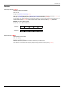
Example: When both the RY and FL terminals are ON: FE07 = 16#0005
Bit Terminal name Function (parameter title) 0 1
0F
[LI F selection] (
F111)
OFF ON
1R
[LI R selection] (
F112)
OFF ON
2RES
[LI RES selection] (
F113)
OFF ON
3 to 6 Reserved - - -
7 VIA (1)
[VIA LI selection] (
F118)
OFF ON
8 to 15 Reserved -
BIT 15 BIT 0
FE06: 0 0000 0000 0000 10 1
000 5
Bit Terminal name (extended) Function (parameter title) 0 1
0RY
Output terminal selection1 (
F130)
OFF ON
1 Reserved - - -
2FL
Output terminal selection3 (
F132)
OFF ON
3 to 15 Reserved - - -
BIT 15 BIT 0
FE07: 0 0000 0000 0000 10 1
000 5