


10
MDS-NT1
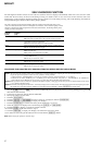
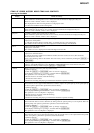
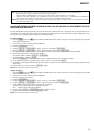
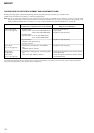
CHECKS PRIOR TO PARTS REPLACEMENT AND ADJUSTMENTS IN MD
Before performing repairs, perform the following checks to determine the faulty locations up to a certain extent.
Details of the procedures are described in “5. Electrical Adjustments”.
Note: This set uses optical pick-up KMS-262E in the production, but for the repair, only the KMS-262A is supplied. As a result, two types of optical
pick-ups are used for this set, and the specified values for the check and adjustment of the laser power vary depending on the type.Details of the
identify of KMS-262A/KMS-262E are described in “5-4. How to Identify Optical Pick-up KMS-262A/KMS-262E”. (See Page 26)
• 0.90 mW power
Specified value : 0.84 to 0.92 mW (KMS-262A)
0.90 to 0.96 mW (KMS-262E)
• 8.40 mW power
Specified value : 8.1 to 8.7 mW (KMS-262A)
8.4 to 8.9 mW (KMS-262E)
• Iop (at 8.4mW)
Labeled on the optical pick-up
Iop value ± 10mA
• Unsatisfactory if displayed as “NG: XXXX”
NG
(XXXX is arbitrary number)
• Unsatisfactory if displayed as “T=@@ (##) [NG”
NG
(@@, ## are both arbitrary numbers)
Laser power check
(5-7-2 : See page 28)
Auto check
(5-7-4 : See page 29)
Temperature
compensation
offset check
(5-7-1 : See page 28)
Criteria for Determination
(Unsatisfactory if specified value is not satisfied)
• Clean the optical pick-up
• Adjust again
• Replace the optical pick-up
• Replace the optical pick-up
• Replace the optical pick-up
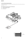
• Check for disconnection of the circuits around
D101 (BD board)
• Check the signals around IC101, IC201, CN102,
CN103 (BD board)
Measure if unsatisfactory:
Note:
The criteria for determination above is intended merely to determine if satisfactory or not, and does not serve as the specified value for adjustments.
When performing adjustments, use the specified values for adjustments.