


32
MDS-NT1
6. Click the [JOG UP] or [JOG DOWN] so that the reading of
the laser power meter becomes specified value, click the
[ENTER/YES] to save it.
Specified Value:
Laser power meter reading: 8.2 to 8.6 mW (KMS-262A)
8.5 to 8.8 mW (KMS-262E)
Note: Do not perform the emission with 8.4 mW more than 15 seconds
continuously.
7. Then, click the [JOG UP] or [JOG DOWN] to display
“LDPWR CHECK” (C13).
8. Click the [ENTER/YES] once to display “L 0.90 mW $ ”.
Check that the reading of the laser power meter become speci-
fied value.
Specified Value:
Laser power meter reading: 0.84 to 0.92 mW (KMS-262A)
0.90 to 0.96 mW (KMS-262E)
9. Click the [ENTER/YES] button once more to display “L 8.40
mW $ ” (KMS-262A) or “L 8.65 mW $ ” (KMS-262E).
Check that the reading the laser power meter and digital volt-
meter satisfy the specified value.
Note down the digital voltmeter reading value.
Specified Value:
Laser power meter reading: 8.4 ± 0.3 mW (KMS-262A)
8.65 ± 0.25 mW (KMS-262E)
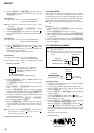
Digital voltmeter reading : Value on the optical pick-up label
±10%
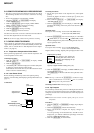
(Optical pick-up label)
10. Click the
[MENU/NO] to display “LDPWR CHECK” (C13)
and stop the laser emission.
(The [MENU/NO] is effective at all times to stop the laser
emission.)
11. Click the [JOG UP] or [JOG DOWN] to display “Iop Write”
(C05).
12. Click the [ENTER/YES]. When the display becomes
Ref=@@@.@ (@ is an arbitrary number), click the [ENTER/YES]
to display “Measu=@@@.@” (@ is an arbitrary number).
13. The numbers which can be changed will blink. Input the Iop
value noted down at step 9.
To select the number : Click the [JOG UP] or [JOG DOWN].
To select the digit : Click the [PUSH].
14. When the [ENTER/YES] is clicked, “Complete!” will be dis-
played momentarily. The value will be recorded in the non-
volatile memory and the display will become “Iop Write”
(C05).
Note: After step 4, each time the [ENTER/YES] is clicked, the display
will be switched “L 0.70 mW $ ” and “LD 7.50 mW $ ”.
Nothing needs to be performed here.
Adjustment Location: BD board (see page 35)
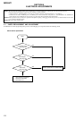
5-13. TRAVERSE ADJUSTMENT
Connection:
Adjusting Procedure:
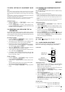
1. Connect an oscilloscope to CN105 pin 4 (TE) and CN105
pin 6 (VC) on the BD board.
2. Load a disc (any available on the market). (Refer to Note 1)
3. Click the [STOP] after the [FF] clicked to move the optical
pick-up outside the pit.
4. Click the [JOG UP] or [JOG DOWN] to display “EF MO
ADJUST” (C07).
5. Click the [ENTER/YES] to display “EFB = MO-R”.
(Laser power READ power/Focus servo ON/tracking servo
OFF/spindle (S) servo ON)
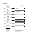
6. Click the [JOG UP] or [JOG DOWN] so that the waveform
of the oscilloscope becomes the specified value.
(When the [JOG UP] or [JOG DOWN] is clicked, the of
“EFB= ” changes and the waveform changes.) In this ad-
justment, waveform varies at intervals of approx. 2%. Adjust
the waveform so that the specified value is satisfied as much
as possible.
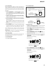
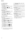
(Read power traverse adjustment)
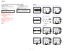
Traverse Waveform
Note 1:Data will be erased during MO reading if a recorded disc is
used in this adjustment.
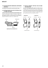
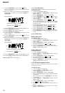
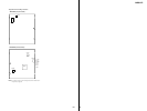
Note 2:If the traverse waveform is not clear, connect the oscilloscope
as shown in the following figure so that it can be seen more
clearly.
+
–
oscilloscop
e
(DC range)
10 pF
330 k
Ω
CN105 pin
4
(TE)
CN105 pin
6
(VC)
BD board
+
–
oscilloscope
(DC range)
V: 0.1 V/div
H: 10 ms/div
BD board
CN105 pin
4
(TE)
CN105 pin
6
(VC)
A
B
VC
Specification A = B
5-12. Iop NV SAVE
Write the reference values in the nonvolatile memory to perform
“Iop compare”. As this involves rewriting the reference values, do
not perform this procedure except when adjusting the laser power
during replacement of the optical pick-up and when replacing the
IC102. Otherwise the optical pick-up check may deteriorate.
Note: Perform this function with the optical pick-up set at room tempera-
ture.
Procedure:
1. Click the [JOG UP] or [JOG DOWN] to display “Iop NV Save”
(C06).
2. Click the [ENTER/YES] and display “Iop [stop]”.
3. After the display changes to “Iop =xxsave?”, click the [ENTER/YES].
4. After “Complete!” is displayed momentarily, the display changes
to “Iop 8.4 mW”.
5. After the display changes to “Iop=yysave?”, click the [ENTER/YES].
6. When “Complete!” is displayed, it means that Iop NV saving
has been completed.
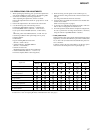
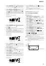
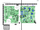
KMS
262A
20101
B0825
Iop = 82.5 mA in this case
Iop (mA) = Digital voltmeter reading (mV)/1 (
Ω
)
(For details of the method for
checking this value, refer to “8.
Recording and Displaying the Iop
Information”.)