


34
MDS-NT1
5-15. ERROR RATE CHECK
5-15-1. CD Error Rate Check
Checking Procedure:
1. Load the check disc (MD) TDYS-1.
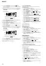
2. Click the [JOG UP] or [JOG DOWN] to display “CPLAY2
MODE” (C36).
3. Click the [ENTER/YES] twice and display “CPLAY2MID”.
4. The display changes to “C = AD = ”.
5. Check that the C1 error rate is below 20.
6. Click the [MENU/NO] to stop playback, then click the [EJECT]
and take out the check disc.
5-15-2. MO Error Rate Check
Checking Procedure:
1. Load the continuously-recorded disc. (Refer to “5-6. USING
THE CONTINUOUSLY RECORDED DISC”)
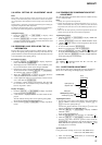
2. Click the [JOG UP] or [JOG DOWN] to display “CPLAY2
MODE” (C36).
3. Click the [ENTER/YES] to display “CPLAY2MID”.
4. The display changes to “C = AD = ”.
5. If the C1 error rate is below 20, check that ADER is 00.
6. Click the [MENU/NO] to stop playback, then click the
[EJECT] and take out the test disc.
5-16. FOCUS BIAS CHECK
Change the focus bias and check the focus tolerance amount.
Checking Procedure:
1. Load the continuously-recorded disc. (Refer to “5-6. USING
THE CONTINUOUSLY RECORDED DISC”)
2. Click the [JOG UP] or [JOG DOWN] to display “CPLAY2
MODE” (C36).
3. Click the
[ENTER/YES] twice to display “CPLAY2MID”.
4. Click the [MENU/NO] when “C = AD = ” is displayed.
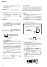
5. Click the [JOG UP] or [JOG DOWN] to display “FBIAS
CHECK” (C16).
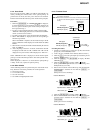
6. Click the [ENTER/YES] to display “ / c = ”.
The first four digits indicate the C1 error rate, the two digits
after “/ ” indicate ADER, and the 2 digits after “c =” indicate
the focus bias value.
Check that the C1 error is below 20 and ADER is below 2.
7. Click the [ENTER/YES] and display “ / b = ”.
Check that the C1 error is about 100 and ADER is below 2.
8. Click the [ENTER/YES] and display “ / a = ”.
Check that the C1 error is about 100 and ADER is below 2
9. Click the [MENU/NO], then click the [EJECT] and take out
the disc.
Note: If the C1 error and ADER are above other than the specified
value at points a (step 8. in the above) or b (step 7. in the above),
the focus bias adjustment may not have been carried out prop-
erly. Adjust perform the beginning again.
5-17. AUTO GAIN CONTROL OUTPUT LEVEL
ADJUSTMENT
Be sure to perform this adjustment when the optical pick-up is
replaced.
If the adjustment results becomes “Adjust NG!”, the optical pick-
up may be faulty or the servo system circuits may be abnormal.
5-17-1. CD Auto Gain Control Output Level Adjustment
Adjusting Procedure:
1. Load the check disc (MD) TDYS-1.
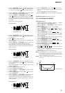
2. Click the [JOG UP] or [JOG DOWN] to display “AG Set (CD)”
(C11).
3. When the [ENTER/YES] is clicked, the adjustment will be
performed automatically.
“Complete!!” will then be displayed momentarily when the
value is recorded in the non-volatile memory, after which the
display changes to “AG Set (CD)” (C11).
4. Click the [EJECT] and take out the check disc.
5-17-2. MO Auto Gain Control Output Level Adjustment
Adjusting Procedure:
1. Load the test disc (MDW-74/GA-1).
2. Click the [JOG UP] or [JOG DOWN] to display “AG Set
(MO)” (C10).
3. When the [ENTER/YES] is clicked, the adjustment will be
performed automatically.
“Complete!!” will then be displayed momentarily when the
value is recorded in the non-volatile memory, after which the
display changes to “AG Set (MO)” (C10).
4. Click the [EJECT] and take out the test disc.