


54
MDS-NT1
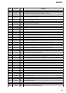
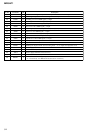
Pin No. Pin Name I/O Description
100 APC O Reference PWM signal output to the RF amplifier for the laser automatic power control
101 LDDR O PWM signal output terminal for laser digital automatic power control Not used
102 TRDR O Tracking servo drive PWM signal (–) output
103 TFDR O Tracking servo drive PWM signal (+) output
104 FFDR O Focus servo drive PWM signal (+) output
105 FRDR O Focus servo drive PWM signal (–) output
106 FS4 O Clock signal (176.4 kHz) output terminal (X’tal system) Not used
107 SRDR O Sled servo drive PWM signal (–) output
108 SFDR O Sled servo drive PWM signal (+) output
109 SPRD O Spindle servo drive PWM signal (–) output
110 SPFD O Spindle servo drive PWM signal (+) output
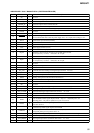
111
FGIN
I
FG input terminal for spindle servo Not used
112 to 11
4
TST1 to TST3 I Input terminal for the test
115 EFMO O EFM signal output terminal when recording mode “L” is output when playback mode
116 VDIO1
— Power supply terminal (+3.3V) (for I/O)
117 VSIO1
— Ground terminal (for I/O)
118 VDC4
— Power supply terminal (+2.5V) (for core)
119 VSC4
— Ground terminal (for core)
120 MDDT1 I
MD data mode selection signal input terminal
“L”: normal mode, “H”: MD data mode (fixed at “L” in this set)