


882.01749.00 12 of 93
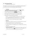
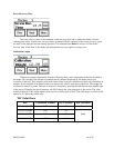
6. EXTRUSION – “Simple”: Connect the input cable (2-conductor cable-gray) to a dry
contact (zero voltage) signal that indicates the extruder
screw is turning. (The connection in the controller should
be on terminal block #10 and PLC input X5.. A jumper wire
can also be installed on the same terminals (instead of a dry
contact.) if the feeder is to be started and stopped through the
feeder controller, and not with the extruder screw.
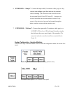
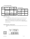
7. EXTRUSION – “Follower”: Connect the input cable (2-conductor cable-gray) to a
0-10 VDC, 0-20 mA, or 4-20 mA signal from the extruder
that indicates the screw speed (rpm) of the extruder. (The
connection inside the controller should be on terminals blocks
51and 54.
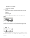
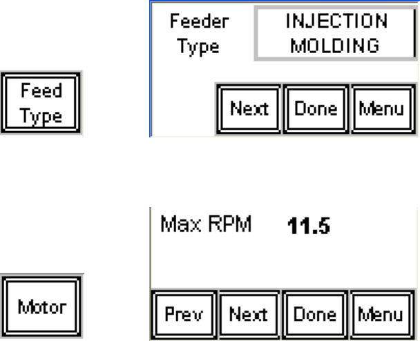
Feeder Configuration - Injection Molding:
Touch the ACS logo on the main menu screen to access the configuration menu. See section # for
details.
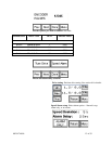
Feeder Type Selection. Select injection molding (default value).
Maximum Motor speed. Enter nominal motor speed.