


882.01749.00 56 of 93
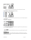
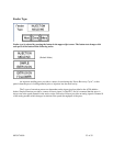
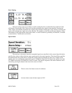
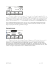
Drive Tuning.
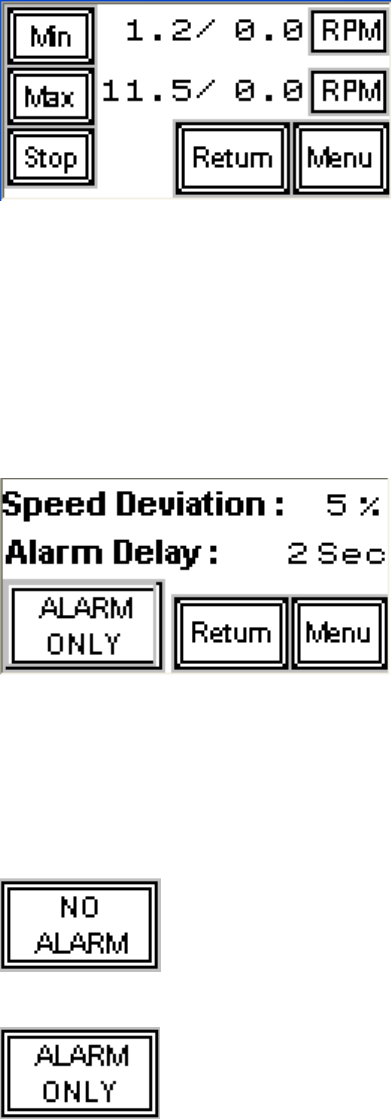
The drive tuning screen is provided as an aid to tuning the drive to match the motor and load of the
A250 feeder. Pressing the “Min” button will send the minimum drive signal to the controller. Pressing the
“Max” button will send the maximum drive signal to the controller. Pressing the “Stop” button (or leaving this
screen) will terminate any signal sent to the controller. The numbers on the left are the target min/max values.
The numbers on the right are the actual speed values. A small screwdriver, preferably non-metallic, is needed
to tune the drive. Tune the drive as follows:
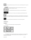
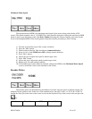
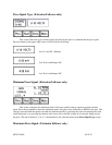
Speed Alarm
The reaction to deviations from the commanded speed are controlled via this screen. Speed deviation
specifies the window within which the motor speed must be for normal operation. The Alarm Delay specifies
the minimum time the speed must be outside this window before generating an alarm. For example, if the
default values are used and the commanded speed is 5 RPM, the controller will alarm if the speed is less than
4.75 RPM or more than 5.25 RPM for at least 2 seconds. The specific response to the alarm condition can be
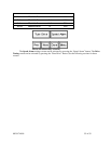
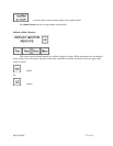
selected by pressing the button in the lower left corner as follows:
Take no action. See Status screens for indicator.
Activate alarm screen & alarm output on PLC.